
Service manual

SECTION 5: PUMP INSTALLATION
9
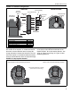
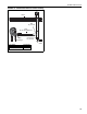
FIGURE 3: Installation Configurations
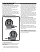
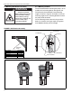
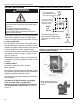
5.2 Pump Impeller Rotation
The rotation of the impeller, as viewed from behind
the motor, must be clockwise when the pump dis-
charge orientation is bottom left horizontal. The rota-
tion of the impeller, as viewed from behind the motor,
must be counterclockwise when the pump discharge
orientation is bottom right horizontal. An arrow label
on the pump scroll indicates the direction of the
impeller rotation. To set the rotation direction, See
Page 14, Figure 13 and Page 15, Figure 15 after
completing Section 5.
FIGURE 4: Pump Impeller Rotation
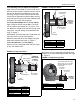
Side View
M8 Screw
Stud
Scroll Assembly
Impeller
Partial End View
Pressure
Switch
M8 Hexnut
and Washer
M8 Hexnut
and Washer
Vertical
Mounting
Plate
Inlet Assembly
Threaded Pipe
Coupling
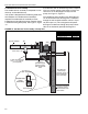
Description Part Number
Pressure Switch 90430600
Pump Scroll 90713451
Hex Nut, M8 (24) 92204502
Washer, M8 x 16 OD x 1.6 95204502
Impeller 90713340
Clockwise RotationCounterclockwise Rotation
Arrow showing direction of rotation
(located on the scroll housing)
Bottom Left Horizontal Discharge PositionBottom Right Horizontal Discharge Position