
Service manual


SECTION 9: VENTING
23 of 33
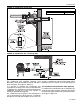
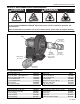
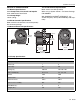
FIGURE 22: Condensate Check Valve
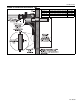
FIGURE 23: Condensate Tee - Discharge Side
9.8 Condensate Trap and Condensate Tee
The condensate trap assembly (optional) (P/N
01327001), should be installed on the inlet side of the
pump assembly, See Page 23, Figure 22.
It is possible to eliminate the condensate trap
assembly on the pump if the one-inch threaded hole
is plugged. This arrangement will permit drainage of
condensate through the pump and outside via
horizontal (pitched) discharge line.
The condensate trap assembly in the discharge line
can be eliminated if the discharge line is horizontal
through the wall and pitched down at least one inch
per foot. A condensate trap on the discharge side is
required if there is a vertical rise in the discharge line.
9.8.1 Condensate Neutralization Tube (optional)
If a condensate neutralization tube is specified to be
used with the heating system, follow the steps below
to choose the proper condensate neutralization tube.
See Page 25, Figure 24.
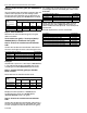
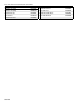
Description Part Number
Condensate Valve Assembly 01327001