
Service manual

EP-300 SERIES PUMP INSTALLATION, OPERATION AND SERVICE MANUAL
16 of 33
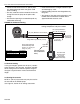
SECTION 8: MOTOR WIRING
All wiring must comply with current wiring regulations
and any local regulations which may apply. Always
switch off the supply and disconnect before servicing.
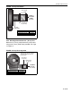
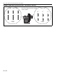
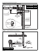
8.1 Impeller Rotation Direction
Prior to operation of the pump in the heating system,
operation and proper rotation of the impeller must be
verified. See impeller rotation direction arrow label on
the pump scroll for the correct rotation direction.
The motor must be wired for clockwise or counterclock-
wise rotation as shown on Page 17, Figure 15 and
Page 18, Figure 17.
IMPORTANT: Improper rotation of the impeller will
not produce the vacuum required for proper system
operation.
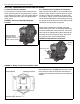
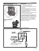
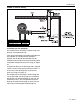
8.2 EP-301 Wiring
The EP-301 motor is wired for 1 Ø, 230 V,
60 Hz operation.
When controlled by a system control, use Contactor
Package 28A (P/N 10050012). See Page 16, Figure
14. See ROBERTS GORDON
®
System Control Manual
(P/N 10091601NA) wiring details.
Wire the pressure switch per the heater Installation,
Operation and Service Manual or appropriate controller
installation manual.
Do not directly connect the controller relay terminals to
the pump motor.
The power to the EP-301 pump is not supplied
by the controller. Power is supplied by a
separate circuit and is switched by the controller
via a contactor with a 120 V AC coil. See Page 16,
Figure 14.
FIGURE 14: EP-301 Contactor Wiring Diagram
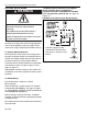
WARNING
Electrical Shock Hazard
Disconnect electrical and gas before
servicing.
This appliance must be connected to a
properly grounded electrical source.
Failure to follow these instructions can result
in death or electrical shock.
Individual supply for pump
rated for total full load current
(See Page 31, Section 12.5 for
details).