
Installation manual
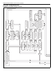


SECTION 9: TROUBLESHOOTING
35
Motor bearings may have
failed. Repace motor.
No
Is the pump impeller
obstructed?
No
Disconnect power to the
motor. Does the motor shaft
turn freely?
Motor may have tripped
overload. Wait 10-15 minutes
and reset.
No
Ye s
Is the pump motor hot?
Rectify wiring between
VFD and pump.
Ye s
No
Is there power between any
two input wires at the pump?
Replace VFD. See section
8.
Ye s
No
Is there 120 V between any
two output (motor)
terminals (U,V or W)?
Refer to the VFD
manufacturer's Installation
and Operation Manual to
clear error.
Replace VFD. See section
8.
Rectify wiring between fuse
holder outputs and VFD
power inputs L1 and L2/N
Replace fuse. See section
8.
Check circuit breaker and
VFD power supply.
No
Ye s
Is there power (120 V or
230 V) between fuse holder
outputs?
No
Ye s
Is there power (120 V or
230 V) between fuse holder
outputs?
No
Ye s
Is there power (120 V or
230 V) between L1 and L2/N
inputs on the VFD?
No
Ye s
Is the LCD display
of the VFD on?
Rectify wiring between
120 V relay and VFD
terminals 1 and 11.
No
Ye s
Is there 120 V between VFD
terminals 1 and 11?
No
Ye s
Is there an error showing
on the LED display?
Replace 120 V relay.
See section 8.
No
Ye s
Is there 120 V between
output terminals on 120 V
relay.
Rectify wiring between
controller and 120 V relay.
No
Ye s
Is there 120 V into 120 V
relay in the variable
frequency drive assembly.
Replace plug-in relay or relay
board. See section 8.
No
Ye s
Is there 120 V at output # 8
on the relay board?
Replace plug-in relay.
See section 8.
Secure wiring between 24 V
Output #8 on control board
and 24 V input connection
#8 on relay board.
Ye s
No
Is there 24 Vac across 24 V
input connection #8 on the
relay board?
No
Verify external wiring
diagrams, Does the pump
turn on?
Ye s
No
Is the red LED on plug-in
relay #8 on the relay board
lit?
Ye s
Ye s
Ye s
Ye s
Ye s