
Installation manual


SECTION 8: REPLACEMENT PARTS
31
SECTION 8: REPLACEMENT PARTS
8.1 ROBERTS GORDON
®
ULTRAVAC™ Controller Replacement Parts
Use only genuine ROBERTS GORDON
®
replacement parts.
Use of parts not specified by Roberts-Gordon voids warranty.
Failure to follow these instructions can result in property damage.
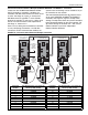
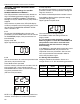
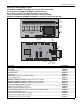
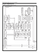
FIGURE 24: ROBERTS GORDON
®
ULTRAVAC™ Controller Components Diagram
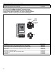
Description
Part Number
Control Board
10080101
Relay Board
10080200
Analog Output Board
10080141
URV Eprom Chip
10080121
Plug-In Relay
10080212
Modem Chip (located only on central controller)
10080142
1 A Fuse (Relay Board)
10080211
ROBERTS GORDON
®
ULTRAVAC™ Indoor Sensor °F (not shown)
10081500
ROBERTS GORDON
®
ULTRAVAC™ Outdoor Sensor (not shown)
10081501
ROBERTS GORDON
®
ULTRAVAC™ Indoor Sensor °C (not shown)
10081502
PC Connection Cable Package (not shown)
10080410
RS-485 Converter Package (not shown)
10080430
TCP/IP Communication Module (not shown)
10080440
Comms Equalization Cable (not shown, located only on Central Controller)
10080450
Telephone Sharing Device, 4 port
10080600
Lamp Socket (for enclosure door, not shown)
91321610
Lamp 24 Vac (for enclosure door, not shown)
91321611
Lens, Red (for enclosure door, not shown)
91321612
POWER
L1 L2 GRD
OUTPUT 1
L1 L2 GRD
OUTPUT 2
L1 L2 GRD
OUTPUT 3
L1 L2 GRD
OUTPUT 4
L1 L2 GRD
OUTPUT 5
L1 L2 GRD
OUTPUT 6
L1 L2 GRD
OUTPUT 7
L1 L2 GRD
OUTPUT 8
L1 L2 GRD
Plug-In
Relays
Control
Board
Analog
Output
Board
URV
Eprom
Chip
Relay
Board
24 V
Power
1 A Fuse
Modem Chip
(only located on
Central Controller)
Run LED
Control Board
Power LED
24 V
Power
Switch
Reset
Button