
Installation manual


SECTION 7: COMMISSIONING THE CORAYVAC
®
SYSTEM
27
SECTION 7: COMMISSIONING THE CORAYVAC
®
SYSTEM
NOTE: The ROBERTS GORDON
®
ULTRA-
VAC™software must be installed on the PC, the
communication connection must be made to the con-
troller and all wiring of the ROBERTS GORDON
®
ULTRAVAC™ control boards, relay boards, burners,
pumps and VFD must be completed before starting
the commissioning procedure.
7.1 Setting The CORAYVAC
®
End Burner Vacuum
It is important to understand that the frequency that
the VFD runs the motor at, determines the speed of
the impeller in the pump. Variation of the impeller
speed will increase or decrease vacuum in the sys-
tem. The following procedure will help you set mini-
mum and maximum VFD frequency settings to
achieve proper vacuum in the system.
Step 7.1.1 At the controller, turn on the 24 V power
switch on the relay board. At the PC, "connect" to the
controller (see the ROBERTS GORDON
®
ULTRA-
VAC™Software Installation and Operation Manual,
P/N 10081600NA for details) and then open the
manual override screen(Alt + M). On the screen,
click the "ON" button for the vacuum pump. Wait 30
seconds then click the ON button for zones 1-3.
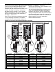
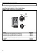
Step 7.1.2 The pump should be running and the
burners should light within 60 seconds. At the VFD,
verify that the number displayed on the LCD screen
is "60.0" If it is lower than 60.0, hit the "up" arrow but-
ton on the VFD until the number reads 60.0 Let the
burners fire for approximately 20-30 minutes to warm
up the system. Using a manometer, check the end
vent vacuum in each zone (each branch of burners).
See Page 28, Figure 22.
If the lowest end vent vacuum reading is above 3.0"
w.c., reduce the vacuum pump speed. Generally the
lowest end vent vacuum reading is on the longest
branch of the system. Use the down arrow button on
the VFD to reduce the frequency of the output signal
to the pump, thus reducing the pump speed and low-
ering the end vent vacuum reading. Continue to
reduce the frequency until the end vent vacuum
reading is between 2.5" - 3.0" w.c. Make note of this
frequency setting below. The frequency is found on
the VFD’s LCD screen.
2.5" w.c. - 3.0" w.c. VFD Frequency Setting
To avoid damage to the pump motor, do not adjust
the frequency above 60.0 Hz. Verify that the end vent
vacuum readings in the remaining branches are
proper. If necessary, adjust the proper damper cou-
pling to achieve an end vent vacuum of 2.5" - 3.0"
w.c. See Page 28, Figure 22. Damper couplings
should be found near the end of the radiant portion of
the pipe in each branch or where a branch connects
to other branches at a cross or tee. See Page 29,
Figure 23.
Record Frequency Setting Here: