
Installation manual


SECTION 5: COMMUNICATIONS
23
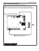
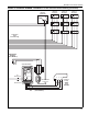
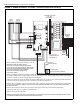
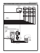
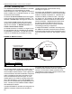
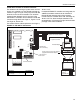
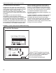
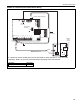
FIGURE 19: TCP/IP Communication Module Wiring
METER
INPUTS
RS-485
+
-
+
-
+
-
+
-
REF
-+-+
+
-
+
-
+
-
+
-
+
-
+
-
RS-232
Direct Port
+
-
+
-
+5
+16
GND
Dip Switch #1
set to ON
8 7 6 5 4 3 2 1
Red +
Black -
RS-45
Jack
Ethernet
Cable
to LAN
RJ-11
Jack
Standard 4 Wire Phone Cord (included)
RED
BLACK
Communications Circuit Equalizer Wiring (included)
1
2
3
4
Shrinkwrap
120 ohm resistor (included)
+
-
module power wire
Red
Black
Red
Black
Description Part Number
TCP/IP Communication Module 10080440
It is important that the module power wire is connected as shown (black=5 V- / red= 5 V+) wire
orientation. Make sure to verify connection before connecting to the control board.