
Installation manual


SECTION 5: COMMUNICATIONS
21
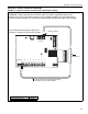
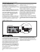
5.2 RS-485 Converter for Central Controller
For remote on-site viewing of system status and set-
tings of any controller, use the RS-485 converter to
connect a single PC (9 pin serial port) to the RS-485
terminals on the Central Controller. This will allow
communication between one PC and any of the
ULTRAVAC™ controllers on the network. For RS-485
converter wiring details see Page 21, Figure 17 and
see Page 25, Section 5.5
For communication cable requirements see Page 11,
Section 3.3.5.
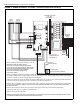
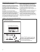
If multiple ULTRAVAC™ controllers are being used, the
additional controllers communicate to controller #1
through RS-485 communication wiring arranged
in-series from one controller to the next.
See Page 25,
Section 5.5
.
This allows multiple controllers to be
controlled from a PC through a single communication
package at the central controller.
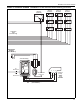
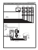
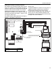
FIGURE 17: RS-485 PC Connection
single
LED
+V
gnd
shld
B
A
(-)
(+)
Windows
®
Compatible PC
METER
INPUTS
ANALOG INPUTS
RS-485
4
3
2
+
1
-
+
-
+
-
+
-
REF-+-+
1
+
-
2
+
-
3
+
-
4
+
-
5
+
-
6
+
-
7
+
-
8
+
-
+5v
Central Controller
25-pin male to 9-pin female adapter
(supplied with RS-485 adapter)
RS-485 Adapter
RS-485 adapter power supply
(supplied with RS-485 adapter)
Wire with white stripe
to positive terminal
9-Pin Female
25-Pin Male
25-Pin Female
(Shield wire
not connected)
To controller #2
Dip Switch #1
set to ON
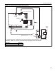
Description Part Number
RS-485 Converter Package with
Power Supply
10080430