
Installation manual


ROBERTS GORDON
®
ULTRAVAC™ CONTROLLER INSTALLATION MANUAL
20
SECTION 5: COMMUNICATIONS
One ROBERTS GORDON
®
ULTRAVAC™ Controller
per building must have equipment for remote
communications to a PC. This equipment consists of
either a modem chip, an RS-485 converter, or a TCP/
IP communications module.
For remote on-site and off-site control and system
status viewing the central controller (controller
#
1) is
fitted with a modem chip. See Page 20, Section 5.1.
If only remote on-site control and system status
viewing, two controller communications interface
devices are available: an RS-485 converter or a
TCP/IP communication module.
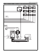
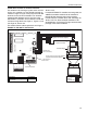
An RS-485 converter is installed at a single PC, this
PC can interface with any controller on the network
of ULTRAVAC™ controllers. The RS-485 converter
at the PC is wired directly to controller #1 using
shielded twisted pair communication wiring.
See Page 21, Figure 17.
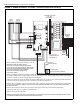
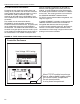
To interface with ULTRAVAC™ controllers through a
Local Area Network (LAN), a TCP/IP Communication
module is installed at controller #1. Controller #1 is
wired to the LAN by an Ethernet cable. See Page
22, Section 5.3. Any computer on the LAN that has
ULTRAVAC™ software installed can communicate
with the controllers. Appropriate precautions must
be taken to protect the Ethernet wiring from any
possible electrical interference (noise) caused by
surrounding machinery or equipment.
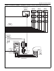
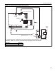
If multiple ULTRAVAC™ controllers are being used,
the additional controllers communicate to controller
#1 through communication wiring arranged in-series
from one controller to the next. See Page 25, Section
5.5.
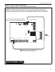
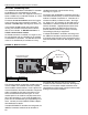
FIGURE 16: Modem Location
5.1
Dedicated Phone Line for Central Controller Modem
The Central Controller is fitted with a modem chip. To
use the modem, the controller must have a phone
line for modem communications. Install a phone line
near the location of the Central Controller. The phone
cable is plugged into the phone connection in the
corner of the control board. See Figure 16. If the
modem option is not used for everyday communica-
tion to the controller(s), it can still be plugged into a
phone line for troubleshooting or programming assis-
tance. Contact your local Roberts Gordon indepen-
dent distributor for details.
If multiple ULTRAVAC™ controllers are being used, the
additional controllers communicate to controller #1
through RS-485 communication wiring arranged
in-series from one controller to the next.
See Page 25,
Section 5.5
.
This allows multiple controllers to be
controlled from a PC through a single communication
package at the central controller.
Dip Switch
#
1
Set to ON
Modem
Chip
Control Board of the
Central Controller
Phone Cable Connection
1 2 3 4 5 6 7 8
Description Part Number
Modem Chip 10080142