
Installation manual


SECTION 4: TYPICAL EXTERNAL DIAGRAMS
19
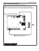
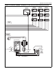
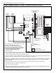
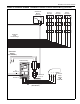
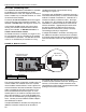
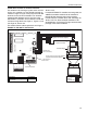
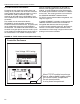
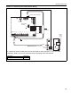
FIGURE 15: ROBERTS GORDON
®
ULTRAVAC™ Satellite Controller External Wiring (continued)
L1L2
Mode
PEWPEVU
PE
EPM
L1 L2/N B+B-
T1
Vacuum
Pump
VFD Assembly
L1L2
L1L2
L1L2
L1L2
L1L2
230 V
3 Ø
0-60 Hz
Outside Air
Blower
(optional)
To
Terminal 5
To
Terminal 2
L1L2
Zone 3
Burners
L1L2
L1L2
VFD Power
Supply
(see NOTE 3)
Zone 2
Burners
Zone 1
Burners
To Terminals
13 and 14
T2 T3
Continued
From
Previous Page
Motor Power Supply
(See NOTE 6)