
Installation manual


ROBERTS GORDON
®
ULTRAVAC™ CONTROLLER INSTALLATION MANUAL
12
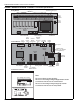
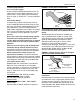
FIGURE 7: RS-485 Communications Cable Detail
3.4 Electrical Installation Requirements
3.4.1 The panel must be supplied from a local fused
isolator rated for a total amperage not
exceeding 25 A.
The method for calculating the current loading is as
follows:
CORAYVAC
®
Burner 0.3 A/burner
Multiply the current for the individual burners above
by the number of burners supplied from the panel to
give the total current required.
The full load amps for the optional outside air blower
(P/N 90707500) are: 1.6 A
The total added current load for each individual
relay must not exceed 3 A.
The total added current load for all 8 relays must
not exceed 25 A.
3.5 Pump Requirements
The pump is powered directly from the Variable
Frequency Drive (VFD). The VFD will be energized
via an output from the relay board switched through a
designated relay.
3.6 Variable Frequency Drive Requirements
The VFD must be powered separately from the con-
trol panel. The 230 V drive power supply must be
230 V, 50-60 Hz, 1 Ø. The 120V drive power supply
must be 120 V, 50-60 Hz, 1 Ø. See Page 9, Section
2.3 for additional details. The VFD on/off switching is
done by an output on the relay board. The 0-10 V
signal from the control panel wired into VFD input
relays 5 and 2 (see Page 16, Figure 12 through Page
19, Figure 15) will dictate the speed of the vacuum
pump. The VFD output supply to the pump is 230 V
3 Ø 0-60 Hz. The frequency of the output supply
signal to the pump will be varied based on the 0-10 V
signal from the control panel. See Page 10, Section
3.2 for additional installation requirements.
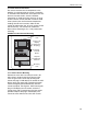
FIGURE 8: Variable Frequency Drive Mounting
Insulation
Foil
Shield
22 AWG
Minimum
Uninsulated
Shield Wire
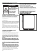
DANGER
Electrical Shock Hazard
Disconnect electrical power before servicing.
This appliance must be connected
to a properly grounded electrical source.
Failure to follow these instructions can result in
death or electrical shock.
6
10 ¾