
Installation manual


SECTION 3: INSTALLATION
11
3.3 Cable Requirements:
3.3.1 Line Power Supply:
As per individual building specification for class of
cable to be used. Use copper conductors only. To
size the cable, use the amperages of the burners
given on Page 12, Section 3.4.1, for each individual
zone.
3.3.2 Control Wiring
All control wiring (sensor, VFD control, pressure
switch and RS-485 communication wiring) may be
plenum or non-plenum rated depending on installa-
tion requirements, consult the National Electric
Code
®
(NEC). Regardless of the code or its interpre-
tation, the local Fire Marshall makes the final deci-
sion, contact the local Fire Marshall if you have
questions.
Do not run control (low voltage) wiring together
with power (line voltage) wiring in the same
conduit. Electrical signal interference or induced
current could occur and cause communication
problems.
VFD (0-10 V) control wiring and all RS-485 com-
munication wiring must be shielded. Shielded
wire provides noise and interference isolation and
reduces the possibility of communication problems.
Sensor and pressure switch wiring is not
required to be shielded. If electrical interference
from machinery or other sources cannot be avoided,
shielded wire must be used. All control cable specifi-
cation diagrams shown will refer to shielded cable.
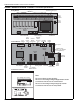
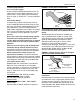
3.3.3 Indoor Sensor Cable:
Shielded cable (four twisted pairs of stranded 24
AWG min. wire) is required for use with indoor
sensors. See Page 11, Figure 5 for an illustration of
the shielded cable specification to be used. See
Page 11, Section 3.3.2 to see if unshielded cable
may be used.
Unshielded Cable:
AMP #57248, #219538,
#219513; Belden # 1585A, #1583A;
General Cable #C6015 or equivalent.
Shielded Cable:
Madison Cable #08CFJ10001, #08CFJ00004;
Belden #9681;
General Cable #2131673, #C1676 or equivalent.
FIGURE 5: Indoor Sensor Cable Detail
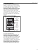
3.3.4 Outdoor Air Sensor VFD (0-10 V) signal,
Pressure Switch Cable and PC RS-485 converter
wiring:
Shielded cable (one twisted pair of 22 AWG min.
wire) is required for the outdoor air sensor, VFD
signal wiring, pressure switch wiring and RS-485
converter wiring between controller #1 and PC
(RS-485 converter wiring to PC is only used if
controller is using an RS-485 Converter
Communication Package). See Page 11, Figure 6 for
an illustration of the cable specification to be used.
Shielded Cable: Belden #8451, #1503A, #8760;
General Cable #C2514 or equivalent.
FIGURE 6: Outdoor Sensor, VFD (0-10 V) Signal
and Pressure Switch Cable Detail
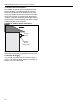
3.3.5 RS-485 Communication Wire Between
Controllers:
Shielded cable (one twisted triad or two twisted pairs
of 22 AWG min. wire) is required for RS-485 commu-
nications between controllers. See Figure 7 for an
illustration of the shielded cable specification to be
used. Shielded Cable: Belden #1902, #8770 General
Cable #C1670 or equivalent.
Shield Wire
Foil
Shield
Insulation
24 AWG
Minimum
Insulation
Foil
Shield
22 AWG Minimum
conductor
(Black = negative)
22 AWG Minimum
conductor
(White = positive)
Uninsulated
Shield Wire