
Installation manual

SECTION 5: COMMUNICATIONS
35 of 62
5.5 Communications Between Multiple ROBERTS GORDON
®
ULTRAVAC™ Controllers
If more than one ROBERTS GORDON
®
ULTRAVAC™ Controller is installed in a building, the
controllers’ RS-485 communications must be wired in
series. See Page 35, Figure 20. Connect the
RS-485 terminal on controller
#
1 to the RS-485
terminal on controller
#
2 and so on in a daisy chain
fashion. For communication cable requirements,
See Page 22, Section 3.3
From a PC, by dialing into the modem on controller
#
1
or by connecting to controller
#
1 via RS-485
converter or TCP/IP communication module, the
system status and settings can be viewed for any of
the controllers on the network.
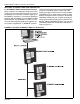
The control board identification dip switch must be
set on each ROBERTS GORDON
®
ULTRAVAC™
Controller. See Page 35, Figure 20 for dip switch
settings. Contact Roberts-Gordon or your
ROBERTS GORDON
®
independent distributor, if
more than 20 controllers are connected.
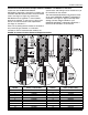
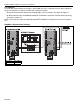
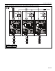
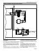
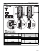
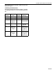
FIGURE 20: Communications Between Multiple Controllers
Controller/Address
Number
Dip Switch Order (1,2,3,4,5,6,7,8)
Values (1=ON, 0=OFF)
11 110100 00
12 00110000
13 10110000
14 01110000
15 11110 000
16 00001000
17 10001000
18 01001000
19 11001000
20 00101000
Controller/Address
Number
Dip Switch Order (1,2,3,4,5,6,7,8)
Values (1=ON, 0=OFF)
1 (Central Controller) 10000000
2 01000000
3 11000000
4 00100000
5 10100000
6 01100000
7 11100000
800010000
910010000
10 01010000