
Service manual


CRV-SERIES DESIGN MANUAL
2
SECTION 2: THE CRV-SERIES SYSTEM
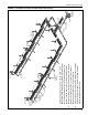
A CRV-Series system consists of one pump, a con-
trol system, and a number of burners, see Page 3,
Figure 1. It also includes an extended tube surface
(4" (10 cm) steel tubing) covered by high efficiency
reflectors to direct the radiant heat downward to the
floor. The tubing nearest the burners radiates with
the most intensity and is called radiant tube. This
should be located over areas with the greatest heat
loss. The rest of the tubing surface (located between
the radiant tube and the pump) radiates with less
intensity and is called tailpipe. This can be located in
areas with lower heat loss.
While it is important to locate radiant tubes over
areas with high heat loss, such as the perimeter of
the building, it is not essential to cover all areas
directly with radiant heat. Center areas (away from
external walls) and other areas of low heat loss can
be adequately heated without direct coverage as
long as the input of the system is adequate for the
total building heat loss. However, to achieve the high-
est degree of comfort and fuel savings, it is recom-
mended that the CRV-Series system be located to
provide as complete and even a distribution as is
practical. In addition, several different reflector and
shield configurations are available to direct the radi-
ant heat to or away from desired areas.
Page 3, Figure 1 illustrates the components of a typi-
cal CRV-Series system. The system shown is a four
burner system composed of two branches. A branch
consists of a single run of tubing, including an end
burner, followed by any burners downstream. A
branch ends at a tee or a cross (where other
branches connect). For a single branch system, the
branch ends at the pump.
2.1 Safety
Safety is a prime consideration of CRV-Series. First,
there is a pre-purge of the complete tube network
prior to flame ignition. Then, to ensure that there will
be no gas flow unless the pump is operating, a pres-
sure switch located at the pump must activate prior to
ignition. After the pressure switch has closed, there
are two valves in-series in each burner that must be
energized, as well as a zero regulator. Additionally,
slow opening gas valves provide smooth ignition and
enhance reliability. Once the thermostat has been
satisfied, the burners turn off and the pump contin-
ues to run for two minutes to purge the entire system
of flue gases.
With CRV-Series, all equipment and controls are
C.S.A. design certified, both as individual parts and
also as a complete heating system. Also, individual
electrical component parts are UL listed, as
applicable.
2.2 Zero Regulator
CRV-Series uses a 100% pre-mix burner with the
input dependent on system vacuum. With no vac-
uum, the zero regulator prevents gas flow. When vac-
uum is present, the burner fires and input increases
as vacuum increases. As the input increases, the
amount of air also increases. Over the normal range
of operating vacuum, the gas/air ratio is essentially
linear.
This unique and patented feature provides optimum
combustion conditions at all times. Combustion con-
ditions are unaffected by fluctuations in fuel pres-
sure, vacuum, dirty air filters, changes in
atmospheric pressure, wind velocity or other climate
conditions.