
Service manual


CRV-SERIES DESIGN MANUAL
32
SECTION 11: CRV-SERIES EQUIPMENT SPECIFICATIONS
The total heating system supplied shall be design
certified by the CSA International per American
National Standard ANSI Z83.20/CSA 2.34 (latest edi-
tion).
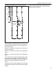
11.1 Burner and Burner Controls
11.1.1 Burners shall be designed to operate simulta-
neously in series without adverse effects from com-
bustion gases from upstream burners.
11.1.2 Burners shall be capable of firing on:
Natural Gas, or LP Gas.
11.1.3 Burners shall be supplied to fire at any one of
the input firing rates as specified:
CRV-B-2 20,000 (Btu/h)
CRV-B-4 40,000 (Btu/h)
CRV-B-6 60,000 (Btu/h)
CRV-B-8 80,000 (Btu/h)
CRV-B-9 90,000 (Btu/h)
CRV-B-10 100,000 (Btu/h)
CRV-B-12A 110,000 (Btu/h)
CRV-B-12 120,000 (Btu/h)
When using ROBERTS GORDON
®
ULTRAVAC
™
controls, burner rates will modulate between 60%
and 100% rated input (CRV-B-2 and CRV-B-4 are not
available for use with ROBERTS GORDON
®
ULTRA-
VAC
™
controls).
11.1.4 The design of burners supplied shall provide
for maintaining a constant proportion of fuel gas to fil-
tered combustion air. These conditions are met for
burners in which the pressure of both the fuel gas
and the combustion air are introduced at zero (atmo-
spheric) pressure and the flow of each is established
by a vacuum on the downstream side of the flow
metering orifices.
11.1.5 To assure a high degree of fail-safe operation,
the design shall preclude flow of gas if any or all of
the following abnormal conditions occur in the non-
firing mode:
1. Main valve fails in open position.
2. Vacuum pump motor fails to operate.
3. Power fails.
11.1.6 To further assure a high degree of safety, the
system will be under negative pressure at all times
during operation to preclude the possibility of the
escape of combustion gases inside the building.
11.1.7 The burner control assembly will include a
zero regulator.
11.1.8 All burners shall be pre-wired with a grounded
electrical cord and plug.
11.2 Equipment
11.2.1 Burner
Each burner assembly shall consist of heavy-duty
cast-iron burner heads, pre-wired gas controls with
electronic, three-try direct spark ignition and com-
bustion air filter.
11.2.2 Pump
The pump model supplied will vary with the capacity
of the system. See the pump technical specification
sheet or the installation, operation and service man-
ual for product description and specification.
The pump shall be acoustically isolated from the sys-
tem with a flexible connector with temperature rating
of 350°F minimum. The motor in the vacuum pump
shall be secured with rubber mounts for acoustical
isolation.
11.2.3 Heat Exchanger
Radiant tubing (between burners and 10’ - 70’ down-
stream of last burner) shall be of 4" O.D. steel or heat
treated aluminized tubing.
As an option, the balance of the tubing shall be 4"
O.D. steel tubing with an internal and external coat-
ing of acid-resistant porcelain.
All heat exchanger (tubing) connections shall be
made with stainless steel coupling assemblies. Stan-
dard couplings will be used in radiant sections. Lined
couplings will be used in tailpipe sections.
11.2.4 Outside Air
When specified, in contaminated environments, the
system shall be capable of supplying air from the
outside to each burner and end vent for the support
of combustion.