
Service manual


CRV-SERIES DESIGN MANUAL
28
SECTION 9: AIR SUPPLY SYSTEM
An air supply free of dust and corrosive contaminants
is essential for proper operation and best life expect-
ancy with any heating system. With CRV-Series,
there are two alternatives available to the designer
for providing the air supply. These are:
• Room Air, A filter is standard for each burner.
• Outside air system to duct air from an uncontami-
nated source. The outside air system can be
designed as a pressurized or non-pressurized
system.
The first alternative above is usable when the dust
load is not excessive and there is no usage of corro-
sive contaminants such as solvents or vapors inside
the building.
The outside air system must be used in all applica-
tions where corrosive contaminants may be present
in the air even in trace amounts (few parts per mil-
lion).
It is important for designers and owners of heating
systems to note that the presence of contaminants in
the combustion air supply will greatly accelerate the
rate of corrosion on tube surfaces and will shorten
the useful life of the heating system. This is true
regardless of whether the heating system is CRV-
Series, other infrared systems or conventional gas or
oil-fired equipment such as unit heaters, central
boiler plant, etc.
With the unique vacuum powered burners, the fuel/
air mix remains constant, even if combustion air fil-
ters are dirty. It can be expected that the use of an
outside air system will reduce but not eliminate the
potential for corrosion due to contamination.
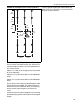
In a way similar to the CRV-Series pump system, the
design of the air supply system also involves consid-
erations of total flow units and acceptable combina-
tions of duct lengths (and diameters) versus flow
units carried. In certain circumstances, it may be
desirable to introduce an outside air blower to pres-
surize the system. A small positive pressure is desir-
able and necessary to prevent the system from
drawing in contaminated air.
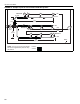
9.1 Pressurized
For pressurized outside air supplies, the outside air
blower motor has a pressure switch that must be
used. Wire this switch in-series with the pump pres-
sure switch. When using an outside air blower with a
ROBERTS GORDON
®
BZC 700, System Control,
ROBERTS GORDON
®
ULTRAVAC
™
or relay trans-
former, a separate load relay package is required.
Wire the control for the relay in parallel with the
pump. The outside air blower must have a separate
20 A, 120 V power supply.
9.2 Non-Pressurized
For a non-pressurized outside air supply, a 4" O.D.
single wall pipe duct may be attached to the burner
and end vent. For length and duct sizing require-
ments See Section 9.3. To prevent condensation,
insulate the outside air duct.
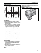
9.3 Outside Air System Design Requirements
9.3.1 Non Pressurized
• 6" diameter duct must not exceed 90' (27 m)
• 4" diameter duct must not exceed 90' (27 m)
• Elbows are equivalent to 10' (3 m) of duct length.
• See the CRV-Series Installation, Operation, and
Service Manual (P/N 127102NA) for ducting
installation details.
9.3.2 Pressurized Systems
• 6" diameter duct must not exceed 120' (36 m)
total per system.
• 4" diameter duct must not exceed 120' (36 m) per
radiant branch.
• See the CRV-Series Installation, Operation, and
Service Manual (P/N 127102NA) for ducting
installation details.