
Service manual


CRV-SERIES DESIGN MANUAL
26
SECTION 8: CONTROL METHODS
There are several methods of controlling CRV-Series
systems. The options are as follows:
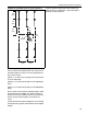
8.1 System Control (P/N 02770002)
The system control is an electronic control panel
dedicated to the control of CRV-Series heating sys-
tems. Control wiring is shown in the system controller
installation manual (P/N 10091601NA). The system
controller can be used to control an EP-100 or EP-
201 pump and control up to four zones.
The electrical requirement is a 120 Vac (20 A) sup-
ply. The output for the thermostat is 12 Vdc. Do not
use thermostats that draw power (power stealing)
from the low voltage supply.
A system control provides two minutes post purge
pump operation to completely exhaust products of
combustion from the system. Indication of power to
the pump, zones and pressure switch status with
lights.
The system control is UL listed.
8.2 ROBERTS GORDON
®
BZC 700 Controller
The ROBERTS GORDON
®
BZC 700 controller is
microprocessor based, pre-programmed to be used
in conjunction with the full range of ROBERTS GOR-
DON
®
radiant heating equipment.
The BZC 700 can be used to control multiple CRV-
Series systems consisting of five zones of burners
and four pumps; six zones and three pumps; or
seven zones and two pumps. The ROBERTS GOR-
DON
®
BZC 700 wiring is shown in the ROBERTS
GORDON
®
BZC 700 Installation Manual (P/N
10071601NA).
The pumps cannot be connected directly to the ROB-
ERTS GORDON
®
BZC 700 controller. Suitable load
relays, contactors or starters are required. Consult
the ROBERTS GORDON
®
BZC 700 Installation
manual (P/N 10071601NA) for details.
The ROBERTS GORDON
®
BZC 700 operated sys-
tem has a two minute post purge pump operation to
completely exhaust products of combustion from the
system. The control offers full energy management
features such as day and night temperature set
points, optimized start up and security coding. For
details of the ROBERTS GORDON
®
BZC 700 fea-
tures and benefits contact your ROBERTS GOR-
DON
®
representative.
The ROBERTS GORDON
®
BZC controller is UL
listed.
The electrical requirement is a 120 Vac (20 A) sup-
ply. Every control requires a ROBERTS GORDON
®
BZC 700 internal temperature sensor (P/N
10001500) in each zone. The sensors must be con-
nected using a shielded cable (Belden 8451 or equiv-
alent).
8.3 ROBERTS GORDON
®
ULTRAVAC
™
The ROBERTS GORDON
®
ULTRAVAC
™
is a micro
processor based control package designed for mod-
ulating control of CRV-Series heaters based on out-
door temperatures. The controls offer full modulation
between 60% and 100% of system maximum rated
input.
This controller is capable of giving control outputs to
one vacuum pump and three heating zones.
System status and settings are viewed and altered
from a PC (not supplied) running ROBERTS GOR-
DON
®
ULTRAVAC
™
Software.
The software requires Windows
®
95 or higher, with a
Pentium
®
class processor and minimum 64k of RAM.
Special design requirements apply for CRV-
Series systems using the ROBERTS GORDON
®
ULTRAVAC
™
Controller, See Page 31, Section 10.
8.4 SPST Transformer Relay (P/N 90417600)
The transformer relay can be used to control an EP-
100 or EP-201 pump CRV-Series system. The single
pole relay can only be used to control one zone of
burners. The wiring diagram is shown in the CRV-
Series Installation, Operation, and Service Manual
(P/N 127102NA).
The electrical requirement is a 120 Vac (20 A) sup-
ply. A transformer relay operated system will not give
any post purge pump operation, or provide indication
of operating conditions.
8.5 DPDT Transformer Relay (P/N 90436300)
The transformer relay can be used to control an EP-
100 or EP-201 pump CRV-Series system. The dou-
ble pole relay can only be used to control two zones
of burners. The wiring diagram is shown in the CRV-
Series Installation, Operation, and Service Manual
(P/N 127102NA).
The electrical requirement is a 120 Vac (20 A) sup-
ply. A transformer relay operated system will not give
any post purge pump operation or provide indication
of operating conditions.