
Service manual


SECTION 7: EXAMPLE CRV-SERIES SYSTEM LAYOUTS
25
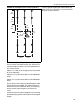
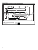
FIGURE 26: Example System Layout (Option 9)
7.7 Example System Layout (Option 7, 8 and 9)
These systems are for B9 burners only, this burner is
specially rated for 2 burners in-series applications in
the systems shown.
Option 7 is a 180' (55 m) straight system connected
to an EP-100 pump.
Option 8 is a system connected to an EP-200 Series
pump.
Option 9 is a system connected to an EP-300 Series
pump.
These layouts show minimum allowed lengths. Addi-
tional tubing may be added. The distance between
the burners can be varied from 30' (9 m) to 20’ (6 m),
but the overall system lengths must remain the
same.
Layout will minimize upfront equipment cost of tubing
by implementing special shortened minimum tailpipe
lengths.
Layout to provide condensed radiant output and
good uniformity of distribution. Layout will exhibit
minimum system efficiency.
30'
(9 m)
30'
(9 m)
10'
(3 m)
30'
(9 m)
10'
(3 m)
30'
(9 m)
30'
(9 m)
6"
Tailpipe