
Service manual

CRV-SERIES DESIGN MANUAL
10
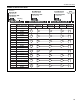
EXAMPLE 2:
Note in Example 2, if equipment had been conven-
tionally sized based on thermal output only, a nearly
identical input requirement would result. For mount-
ing heights above 60' (18 m), no further correction is
generally necessary if the floor level radiant intensity
is sufficient to establish a reserve capacity (hence,
radiant comfort), and the heat loss
requirement is satisfied based on thermal output.
Due to the complexity of installations with mounting
heights over 60' (18 m), it is advisable to contact
Roberts-Gordon for further information regarding the
specific application.
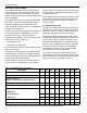
4.3 Selecting the Burners
The number of burners and input for each must be
specified in the design layout. The following
factors should be considered when selecting burner
input:
• Heat gain and distribution required.
• Mounting height.
• Flow loading restrictions.
• Length of radiant branches.
• Distance required between burners.
• Desired radiation intensity.
In general, lower burner inputs can be used for lower
mounting heights and where lower heat gains are
required. Higher burner inputs are used primarily
with higher mounting heights and where high heat
gain is required.
The number of burners required can be calculated by
dividing the input rating of the selected sizes into the
calculated CRV-Series system required installed
capacity.
4.4 Radiant Distribution
Radiant heat distribution at occupant level must be
considered in the burner and design selection
process.
Distribution of heat between radiant branches at floor
level is more critical at the perimeter of buildings.
This is where the heat loss is highest. Therefore, it
may be possible to combine different applications of
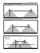
distribution within the same building. The following
figures show three different applications of rules to
determine distribution.
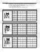
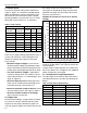
4.4.1 Radiant Distribution (Average Coverage)
The aim of this distribution is to provide average or
lighter than average radiant intensity and works well
for general building heating. See Page 11, Figure 11.
The distance between radiant branches can vary
between 2.5 to 4 (or more) times the mounting
height.
This distribution is commonly used in applications
such as warehouses and lower heat loss areas of a
building.
Lighter coverage can be used in areas where occu-
pant traffic is low.
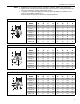
4.4.2 Radiant Distribution (Increased Coverage)
The aim of this distribution is to provide continuous
radiant intensity. See Page 11, Figure 12. The
distance between radiant branches is about 2 times
the mounting height.
This distribution is commonly used in areas border-
ing high heat loss areas or areas requiring increased
radiant intensity to achieve occupant comfort.
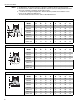
4.4.3 Radiant Distribution (Heavy Coverage)
The aim of this distribution is to provide increased
radiant intensity in areas that range from sedentary
work to spot heating for loading docks. See Page 11,
Figure 13. The y dimensions in the diagram is the
height above floor level where overlap of the radiant
output will occur.
In practice, y = 6' (1.83 m) is commonly used in areas
where occupant comfort doing sedentary work is an
important factor. In loading bays, spot heating and
areas of high heat loss, the horizontal distance (x)
between branches can be as little as 0.5 times the
mounting height.
Given a building with a calculated heat loss
of 500,000 Btu/h, what is the installed
capacity required of a CRV-Series system
mounted at 50' (15 m)?
CORAYVAC
®
Installed Capacity = Heat Loss x
Radiant Adjustment x Height Adjustment.
For CORAYVAC
®
systems, a .80 radiant adjust-
ment factor is used.
The height adjustment is 1% per foot over 20'
(3% per meter over 6 meters), or 1.30.
∴ CORAYVAC
®
Installed Capacity = 500,000
(Btu/h) x .80 x 1.30 = 520,000 (Btu/h).