® CoRayVac Custom Engineered, Gas-Fired, Low-Intensity Infrared Heating System CRV-B-2 CRV-B-9 CRV-B-4 CRV-B-10 CRV-B-6 CRV-B-12 CRV-B-8 CRV-B-12A Design Manual ® All designs must be installed in strict accordance with the CORAYVAC Installation, Operation and Service Manual (P/N 127102NA). Roberts-Gordon 1250 William Street P.O. Box 44 Buffalo, New York 14240-0044 Telephone: 716.852.4400 Fax: 716.852.0854 Toll Free: 800.828.
TABLE OF CONTENTS SECTION 1: Concept .............................................................. 1 SECTION 2: The CRV-Series System .................................... 2 2.1 Safety........................................................................... 2 2.2 Zero Regulator............................................................. 2 2.3 Fuel Savings and Comfort ........................................... 4 SECTION 3: Critical Considerations ..................................... 5 3.
TABLE OF FIGURES Figure 1: Assembly Overview (Two Branch System Shown)...........................3 Figure 2: Standard Reflector ...........................................6 Figure 3: One Side Reflector ..........................................6 Figure 4: Two Side Reflectors .........................................6 Figure 5: Universal Shield, Position 1 .............................7 Figure 6: Universal Shield, Position 2 .............................7 Figure 7: Universal Shield, Position 3 ..............
SECTION 1: CONCEPT SECTION 1: CONCEPT The concept of CRV-Series is easy to understand. However, it means discarding old ideas because CRV-Series is a different kind of heating system. CRV-Series is a gas-fired, vacuum-operated, lowintensity infrared heating system incorporating a patented incremental burner system. Gas-Fired means it uses clean-burning Natural or Propane gas. Vacuum-Operated means that the pump draws all the products of combustion through the system and expels them outdoors.
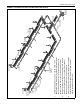
CRV-SERIES DESIGN MANUAL SECTION 2: THE CRV-SERIES SYSTEM A CRV-Series system consists of one pump, a control system, and a number of burners, see Page 3, Figure 1. It also includes an extended tube surface (4" (10 cm) steel tubing) covered by high efficiency reflectors to direct the radiant heat downward to the floor. The tubing nearest the burners radiates with the most intensity and is called radiant tube. This should be located over areas with the greatest heat loss.
Coupling Reflector Support Burner 3. Plain couplings are used to connect combustion chambers to radiant tubing and radiant tubing to tailpipe tubing. All tailpipe couplings must be lined. 2. Damper couplings are required when layout has unequal branches. Unequal branches are achieved by unequal geometry, burner quantity or burner firing rates. 1. Radiant tubing between burners, and 20-50' (6-15 m) downstream of the last burner is normally hot rolled steel or heat-treated aluminized steel.
CRV-SERIES DESIGN MANUAL 2.3 Fuel Savings and Comfort Space heating can be accomplished with less input capacity when a radiant heating system is utilized, rather than with a conventional convective heating system. Why is this so? A conventional, convective heating system, such as a unit heater or central furnace works by heating the air, which then indirectly heats the area and occupants. CRV-Series utilizes infrared energy to heat objects, people and surfaces directly, not the air.
SECTION 3: CRITICAL CONSIDERATIONS SECTION 3: CRITICAL CONSIDERATIONS 3.1 Required Clearances to Combustibles Clearances are the required distances that combustible objects must be away from the heater to prevent serious fire hazards. Combustibles are materials, which may catch on fire and include common items such as wood, paper, rubber, fabric, etc. Maintain clearances to combustibles at all times for safety.
CRV-SERIES DESIGN MANUAL NOTE: 1. All dimensions are from the surfaces of all tubes, couplings, elbows, tees and crosses. 2. Clearances B, C and D can be reduced by 50% after 25' (7.5 m) of tubing downstream from where the combustion chamber and the tube connect. 3. “-” indicates an unapproved application. Roberts-Gordon prohibits the installation of this heater for all unapproved applications. * Protective Grille clearances are the same as Standard Reflector.
SECTION 3: CRITICAL CONSIDERATIONS NOTE: 1. All dimensions are from the surfaces of all tubes, couplings, elbows, tees and crosses. 2. Clearances B, C and D can be reduced by 50% after 25' (7.5 m) of tubing downstream from where the combustion chamber and the tube connect. 3. “-” indicates an unapproved application. Roberts-Gordon prohibits the installation of this heater for all unapproved applications. * Protective Grille clearances are the same as Standard Reflector.
CRV-SERIES DESIGN MANUAL NOTE: 1. All dimensions are from the surfaces of all tubes, couplings, elbows, tees and crosses. 2. Clearances B, C and D can be reduced by 50% after 25' (7.5 m) of tubing downstream from where the combustion chamber and the tube connect. 3. “-” indicates an unapproved application. Roberts-Gordon prohibits the installation of this heater for all unapproved applications. * Protective Grille clearances are the same as Standard Reflector.
SECTION 4: SIZING AND DESIGN CONSIDERATION SECTION 4: SIZING AND DESIGN CONSIDERATION heating system. The ability of a radiant system to The building heat loss must be calculated in accordance to accepted energy load calculation methods. provide the advantages of these radiant effects rests largely with the ability of this system to establish a ASHRAE (American Society of Heating, Refrigeration and Air-Conditioning Engineers) offers in-depth reserve heat capacity in the floor.
CRV-SERIES DESIGN MANUAL EXAMPLE 2: Given a building with a calculated heat loss of 500,000 Btu/h, what is the installed capacity required of a CRV-Series system mounted at 50' (15 m)? CORAYVAC® Installed Capacity = Heat Loss x Radiant Adjustment x Height Adjustment. For CORAYVAC® systems, a .80 radiant adjustment factor is used. The height adjustment is 1% per foot over 20' (3% per meter over 6 meters), or 1.30. ∴ CORAYVAC® Installed Capacity = 500,000 (Btu/h) x .80 x 1.30 = 520,000 (Btu/h).
SECTION 4: SIZING AND DESIGN CONSIDERATION FIGURE 11: Radiant Distribution (Average Coverage) H= mounting height 3H 90° H FIGURE 12: Radiant Distribution (Increased Coverage) H= mounting height 2H 90° H FIGURE 13: Radiant Distribution (Heavy Coverage) H= mounting height y= height above the floor level where overlap of radiant output will occur x=2H-2y x H 90° y 11
CRV-SERIES DESIGN MANUAL SECTION 5: FLOW LOADING The patented CRV-Series burner system allows a number of burners to be installed in-series, in the same radiant tube, resulting in a long, continuous radiant emitting surface to give even heat distribution within the building. burners, the burner inlet flow consists the of the total of the end vent air plus the combustion gases from all upstream burners.
SECTION 5: FLOW LOADING FIGURE 14: Burner Flow Units B-10 Burner #1 End Burner End Vent Air B-10 Burner #2 B-10 Burner #3 Combustion Gas Combustion Gas Downstream Burner + 20 Flow Units Combustion Gas Downstream Burner + 10 Flow Units + 10 Flow Units Total Flow Units 20 + 10 + 10 + 10 = 50 Flow Units + 10 Flow Units Coupling Burner 1 Burner 2 Burner #2 Flow Units Burner 3 Burner # Burner Firing Rate Btu/h End Vent Flow Units 1 2 3 20,000 20,000 20,000 6 2 2 2 12 1 2 3 40,000 4
CRV-SERIES DESIGN MANUAL 5.2 Pump Capacity the number of flow units carried in the tube. The flow unit capacity of the pump is indicated on Page 14, Table 2, as a function of installed altitude. When the CRV-Series system is designed in accordance with this set of instructions and is in proper operating condition, a vacuum from 2-3" w.c. will be obtainable at each end vent (i.e. at all burners). See Figure 15.
SECTION 6: RADIANT TUBE AND TAILPIPE SECTION 6: RADIANT TUBE AND TAILPIPE The main purpose of the tailpipe and the radiant tube is to provide sufficient tube surface to transfer the heat from the flue gases to the tube wall where it radiates from the tube. Radiant tube is defined as the tubing between burners firing in a radiant branch, plus the radiant tubing immediately following the last downstream burner. Tailpipe is defined as all tubing between the radiant tube and the pump.
CRV-SERIES DESIGN MANUAL FIGURE 16: Tube Length vs. Efficiency ip e ip e n e ip P t Ma xim um Ra Ra di ina l No m 2.0 di a an tP nt P dia Ra 2.5 Mi nim um Length of Tailpipe per Flow Unit (feet) 3.0 1.5 1.0 83% 84% 85% 86% 87% 88% 89% 90% Steady State Thermal Efficiency (%) NOTE: Thermal efficiency values shown do not include the contribution due to condensing conditions when operating in cyclic fashion.
SECTION 6: RADIANT TUBE AND TAILPIPE 4. Select pump model series for total system flow units: EP-100: up to 66 flow units EP-200: up to 110 flow units EP-300: up to 224 flow units 5. See Page 14, Table 2 for altitudes greater than 2000'. 6. For each branch, add the length of radiant tube after each heater: Radiant Tube Length Burner After Each Burner 1 + 2 + 3 + 4 + 5 + 6 + Total Radiant Tube Length in Branch = Repeat this calculation for each branch in the system. 7.
CRV-SERIES DESIGN MANUAL EXAMPLE 3: B-10 Radiant Tube vs. Tailpipe Length For a B-10 burner system of 200 flow units and an average of 40' radiant tube length per burner, See Page 17, Table 4 for the tailpipe lengths per flow unit that can be used and the corresponding operating characteristic. From Table 4, we can use between 1.2' per flow unit and 2.5' per flow unit when the average radiant length per B-10 burner is 40'.
SECTION 6: RADIANT TUBE AND TAILPIPE 6.5.4 To Check Performance Criteria Total system tailpipe = Tailpipe ft/flow unit Total flow units Compare the results to Page 17, Table 4 and Page 18, Table for the burner model to ensure that the resulting tailpipe lengths maintain intended operating characteristic. 6.5.
20 Damper Zone 1 Damper Coupling NOTE: Damper setting will vary Zone 1 Damper Coupling Zone 2 Zone 2 Damper Coupling Zone 1 End Vent Zone 3 Damper Coupling Pump Damper Zone 3 Zone 2 End Vent Zone 3 End Vent CRV-SERIES DESIGN MANUAL FIGURE 17: Possible Damper Coupling Locations
SECTION 7: EXAMPLE CRV-SERIES SYSTEM LAYOUTS SECTION 7: EXAMPLE CRV-SERIES SYSTEM LAYOUTS Systems that are symmetrical are preferred because FIGURE 18: Example System Layout (Option 1) the vacuum available in the system branches are balanced as a function of design (damper couplings are not needed). Where radiant tube lengths are variable in a single branch, the average length shall be used to determine the total radiant tube length.
CRV-SERIES DESIGN MANUAL FIGURE 19: Example System Layout (Option 2) 40' (12 m) 10' (3 m) 40' (12 m) FIGURE 20: Example System Layout (Option 3) 30' (9 m) 20' (6 m) 40' (12 m) 40' (12 m) 30' (9 m) 30' (9 m) 40' (12 m) 40' (12 m) 50' (15 m) 6" Tailpipe 40' (12 m) 7.2 Example System Layout (Option 2) Six B10 burners at recommended radiant tube length and 1.2'/flow unit tailpipe, the recommended pump for this system is an EP-200 Series pump.
SECTION 7: EXAMPLE CRV-SERIES SYSTEM LAYOUTS FIGURE 21: Example System Layout (Option 4) FIGURE 22: Example System Layout (Option 5) 30' (9 m) 40' (12 m) 30' (9 m) 40' (12 m) 30' (9 m) 40' (12 m) 70' (21 m) 30' (9 m) 30' (9 m) 30' (9 m) 40' (12 m) 6" Tailpipe 10' (3 m) 7.4 Example System Layout (Option 4) Nine B10 burners at recommended radiant tube length and 1.58'/flow unit tailpipe, the pump for this system is an EP-300 Series Pump. All shared tailpipe is 6" diameter.
CRV-SERIES DESIGN MANUAL Layout to provide minimum system efficiency. Adjust the lengths as necessary for different input systems and to increase the efficiency levels. This layout method is often used effectively in heatloss and perimeter heating applications.
SECTION 7: EXAMPLE CRV-SERIES SYSTEM LAYOUTS FIGURE 26: Example System Layout (Option 9) Layout to provide condensed radiant output and good uniformity of distribution. Layout will exhibit minimum system efficiency. 30' (9 m) 30' (9 m) 10' (3 m) 30' (9 m) 10' (3 m) 6" Tailpipe 30' (9 m) 30' (9 m) 7.7 Example System Layout (Option 7, 8 and 9) These systems are for B9 burners only, this burner is specially rated for 2 burners in-series applications in the systems shown.
CRV-SERIES DESIGN MANUAL SECTION 8: CONTROL METHODS There are several methods of controlling CRV-Series systems. The options are as follows: 8.1 System Control (P/N 02770002) The system control is an electronic control panel dedicated to the control of CRV-Series heating systems. Control wiring is shown in the system controller installation manual (P/N 10091601NA). The system controller can be used to control an EP-100 or EP201 pump and control up to four zones.
SECTION 8: CONTROL METHODS 8.6 Pressure Switch A pressure switch is required to confirm pump operation on all systems. A pressure switch is also required on the inlet duct of a non-pressurized air supply.
CRV-SERIES DESIGN MANUAL SECTION 9: AIR SUPPLY SYSTEM An air supply free of dust and corrosive contaminants is essential for proper operation and best life expectancy with any heating system. With CRV-Series, there are two alternatives available to the designer for providing the air supply. These are: • Room Air, A filter is standard for each burner. • Outside air system to duct air from an uncontaminated source. The outside air system can be designed as a pressurized or non-pressurized system.
SECTION 9: AIR SUPPLY SYSTEM FIGURE 27: Air Supply System Capacity by Duct Length and Diameter NOTE: For capacity requirements larger than shown, use 8" duct. or EP-200 series pump and two outside air blowers may be required for each EP-300 series pump. Outside air blowers cannot be shared between two separate CRV-Series systems. FIGURE 28: Outside Air Blower 140 100 7" 80 60 6" 40 5" 20 0 4" 0 50 100 150 200 Straight Duct Length (feet) Duct Diameter Flow Units 120 250 9.3.
CRV-SERIES DESIGN MANUAL FIGURE 29: Sample Layout for Pressurized Outside Air Systems Branch A 20 8 8 8 6" duct 4" duct 15' (4.5 m) 110' (33 m) B 10' (3 m) max.* 50' (15 m) (44) 4" duct Branch B 15 6 6 6 P (33) (22) 4 4 4 10 Branch C 4" duct 100' (30 m) *NOTE: up to 10' (3 m) max. from blower inlet can be neglected for pressure drop calculations.
SECTION 10: ROBERTS GORDON® ULTRAVAC™ DESIGN REQUIREMENTS SECTION 10: ROBERTS GORDON® ULTRAVAC™ DESIGN REQUIREMENTS CRV-B-2 and CRV-B-4 are not available for use with ROBERTS GORDON® ULTRAVAC™ controls. CRV-Series systems designed with minimum radiant tube lengthshall have 1.5' - 2.0' per flow unit of tailpipe length. -ORCRV-Series systems with recommended radiant tube length shall have 1.2' - 1.5' per flow unit of tailpipe length.
CRV-SERIES DESIGN MANUAL SECTION 11: CRV-SERIES EQUIPMENT SPECIFICATIONS 11.1.8 All burners shall be pre-wired with a grounded The total heating system supplied shall be design electrical cord and plug. certified by the CSA International per American National Standard ANSI Z83.20/CSA 2.34 (latest edi- 11.2 Equipment tion). 11.2.1 Burner 11.1 Burner and Burner Controls Each burner assembly shall consist of heavy-duty 11.1.