
Service manual


ROBERTS-GORDON SECTION 4: DESIGN REQUIREMENTS pg 5
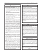
Figure 1. Illustrative View of Typical VANTAGE
®
EV Installation
Table 1. Design Requirements
Burner Model: EV-80 EV-110 EV-140 EV-170 EV-200
Maximum # of Burners Allowed per Vacuum Pump (EP-100) 44422
Maximum # of Burners Allowed per Vacuum Pump (EP-200) 66644
Radiant Tube Length (ft.) 30 40 50 60 70
Maximum Manifold Length (ft.) 20 20 20 30 30
Minimum Distance from Burner to Elbow (ft.) 20 20 20 20 20
Elbows Allowed per Burner 22222
Zone 1 Burner
Transition Tube
Zone 1 Thermostat
Electronic Control Panel
(optional)
Vacuum Pump
Exhaust to Outside
Coupling
Radiant Tube
Damper Couplings
(if necessary)
Tee
Manifold Pipe
(coated or aluminized)
Turbulator
Radiant Tube
Elbow
Radiant Tube
Zone 2 Burner
Zone 2
Thermostat
Transition Tube
Turbulator
Radiant Tube
Section 4. Design Requirements
EV-Series systems are typically shipped as burner
packages and tube and accessory packages. The tube
and accessory packages contain enough tube and
reflector and hanging parts for one EV burner. Elbows,
tees, tailpipe, vacuum pumps, controls, and any other
parts must be purchased separately. See Figure 1 below
for a general overview of a simple EV system. Depending
on system requirements, EV systems may be controlled
by either the control panel (shown) or by a relay system.
A number of radiant tube sections are interconnected by
manifold sections to a vacuum pump to form a complete
system. Reflectors can be used over the manifold pipe
but are not required. The system design parameters are
such that the manifold sections are not subjected to
condensate. As a precaution, it is recommended that
aluminized heat-treated or coated tubing is used for the
manifold to increase system life and to handle the initial
condensation during start-up. Damper couplings may be
necessary to balance system vacuum.
Table 1 below summarizes the design requirements for a
VANTAGE
®
EV system. For “mixed” systems: the number
of burners allowed corresponds to the number of burners
allowed for the particular pump and the LARGEST firing
rate being used.