
Service manual


ROBERTS-GORDON SECTION 10: GAS PIPING pg 27
Section 10. Gas Piping
Read applicable warnings in Section 1 before proceeding
with Gas Piping installation. Improper installation will
result in death, severe injury or property damage.
Meter and service must be large enough to handle all the
burners being installed plus any other connected load. The
gas line which feeds the system must be large enough to
supply the required gas with a maximum pressure drop of
1/2" w.c. When gas piping is not included in the layout
drawing, the local gas supplier will usually help in planning
the gas piping.
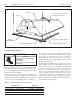
Flexible Gas Connector Assembly
Shut-Off Valve
(included with connector)
2" (5 cm)
12"
(30 cm)
Shut-Off Valve must be parallel to burner gas inlet.
The 2" (5 cm) displacement shown is for the cold
condition. This displacement may reduce when the
system is fired.
45°
0°
45°
90°
Figure 25. Gas Line Connection with Flexible Gas Connector Assembly
A 1/2" (EV-80 & -110) or 3/4" (EV-140, -170 & -200) gas
supply connection at each burner location must be
located and oriented as shown in Figure 25. To check
system pressure, put a plugged 1/8" NPT tapping in the
gas line at the connection to the burner furthest from the
supply. Before connecting the burners to the supply
system, verify that all high pressure testing of the gas
piping has been completed.
Follow these instructions to ensure a professional gas
supply system installation:
• Support all gas piping with suitable pipe hanging
materials.
• Use wrought iron or wrought steel pipe and malleable
iron fittings. All pipe and fittings should be new and free
from defects. Carefully ream the pipe and tubing ends
to remove obstructions and burrs.
• Use LP-gas-resistant joint compound on all threads.
• Check the pipe and tubing ends for leaks before
placing heating equipment into service. When checking
for gas leaks, use a soap and water solution; never use
an open flame.
Install the flexible gas connector assembly as shown. This
gas connector accommodates expansion of the heating
system and allows for easy installation and service of the
burner.
WARNING
Fire Hazard
Connect gas according to
Figure 25.
Gas line moves during normal
operation
Failure to follow these
instructions will result in death,
injury or property damage.
Explosion Hazard
Do not high pressure test the
gas piping with the burner
connected.
Failure to follow these
instructions will result in death,
injury or property damage.