
Service manual


VANTAGE
®
EV INSTALLATION MANUAL ROBERTS-GORDONpg 26
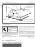
Flex Pipe
6" to 12" Long
Outside Air Terminal
Band Clamp
Burner Assembly
HORIZONTAL INSTALLATION
Roof
Wall
VERTICAL INSTALLATION
Flex Pipe
6" to 12" Long
Band Clamp
Burner
Assembly
Sweeping Tee Connection
Sweeping 'Y' Connection
6"
Outside Air Terminal
6"
4"
4" Single Wall Pipe
(Seal All Joints)
4"
4"
Figure 24. Non-Pressurized Outside Air Supply for a Maximum of Two Heaters Controlled by a Common Thermostat
Outside Combustion Air Supply (Continued)
When air is supplied for combustion to a maximum of two
heaters through a common duct, the following rules
apply:
1. Follow the venting rules on page 21 for detailed
guidelines.
2. The two units must be controlled by a common
thermostat.
3. Use 4” O.D. (10 cm O.D.) single wall or PVC pipe
between the heater connection and the common
source. The common source will be a minimum of
6” O.D. (15 cm O.D.) single wall or PVC pipe.
4. Combined length of the 4” and 6” pipe shall not
exceed 45 feet (13.7 m) with 2 elbows maximum
per unit (see Figure 24). See also Vent Length
Requirements heading on page 22 for more
detailed guidelines.
5. Entry of the 4” pipes will not oppose one another.
Example: 4 feet of 6” O.D. (15 cm O.D.) common
supply air pipe and one 6”x4”x4” tee are
attached to 4” pipe x 4 feet long,
attached to EV units. This will limit the
flue length to 45 feet of 4” pipe.