
Service manual


ROBERTS-GORDON SECTION 9: VENTING AND DUCTING pg 25
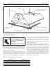
Figure 23. Outside Air Supply Duct
Outside Combustion Air Supply
IMPORTANT: If the building has a slight negative
pressure or contaminants are present in the air, an
outside combustion air supply to the heaters is strongly
recommended.
Some compounds such as halogenated hydrocarbons or
other corrosive chemicals in the air can be drawn into the
equipment and cause an accelerated rate of corrosion of
some of the heater components. The use of such
chemical compounds near the enclosure should be
avoided.
Non-Pressurized Outside Air Supply
For an outside air supply, a 4" O.D. single wall pipe may
be attached to the heater. The duct may be up to 45 ft.
maximum length or 2 ft. minimum length with no more
than 2 elbows. See General Requirements heading on
page 21 for more detailed guidelines. An outside air
supply should not be used with the draft hood venting
configuration.
The air supply duct may have to be insulated to prevent
condensation on the outer surface. The outside air
terminal should be securely fastened to the outside wall
by drilling four 1/4" diameter holes in the outside flange;
wood screws or bolts and expansion sleeves may be
used to fasten the terminal.
Pressurized Outside Air Supply
If a pressurized outside air supply is desired, the air
supply system should be installed as indicated on the
heating plans. If there are any questions, consult the
sales representative.
When a pressurized outside air supply is required, the
optional electronic control panel should be used to
facilitate installation and control.
Flex Pipe
6" to 12" long
4" Flue Pipe
Seal All Joints
Outside Air
Terminal
Roof
Wall
6" Inlet
6" Discharge
Motor
Air Pressure Switch
Burner Box
Outside Air Collar
Outside Air Terminal: Use Metalbestos #31267
(RG P/N 90502300), or equivalent. PVC pipe,
“dryer hose”, or equivalent may be used instead
of standard vent pipe.
Important: Outside air terminal must not be
located higher than vent terminal.
If used, the outside air supply blower (P/N 90707500
should be wired in parallel with the vacuum pump,
and in accordance with the National Electric Code
and local ordinances. The blower air pressure switch
should be wired in series with the vacuum proving
switch on the vacuum pump.
All joints and seams in the air supply system must
be made airtight, preferably by use of duct tape. See
above instructions on attaching duct to the burner.
Mount the blower according to the manufacturer’d
instructions. Additional mounting materials should be
provided by the contractor.