
Service manual


VANTAGE
®
EV INSTALLATION MANUAL ROBERTS-GORDONpg 18
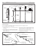
I-Beam
I-Beam
Beam Clamp
S-Hook
Truss
Anchor
Bar Joist Clip
Concrete Beam
Locknut
Washer
Screw Hook
min. 3/8" (10mm)
Washer
Wood Beam
Turnbuckle
(not included)
24" (60cm)
minimum
12" (30 cm)
minimum
3/16" or
larger
Chain
Figure 15. Typical Suspension Details
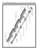
Figure 16. Turbulator Baffle Assembly Detail
Turbulator adapter piece
Turbulator 2.5 ft.
section pieces
(3 sections plus
one adapter piece)
Last standard section of
heat exchanger tubing
Attach a wire to this tab.
TO BURNER
Pull turbulator into
tube using long wire
Lock tab in place
with next coupling
“Twist-lock”
sections together
TO VACUUM
PUMP
Turbulator Installation
For ease of installation, the turbulator should be installed in the tube before hanging the system.
Use the following procedure (see Figure 16):
1. Assemble turbulator pieces by “twisting” matching
ends together.
2. Insert a long wire (11 ft. minimum) down the length of
the tube. Attach the wire to the hole in the tab on the
turbulator adapter piece.
3. Using the wire, pull the assembled turbulator into the
tube from the opposite end. Pull the turbulator through
until just the tab comes out. Detach the wire.
4. Bend the tab around the tube. When installed the next
coupling will lock the tab in place.