
Service manual


VANTAGE
®
EV INSTALLATION MANUAL ROBERTS-GORDONpg 16
Section 8. Component Installation
Tube Coupling Installation
Tube and tube fittings are connected by wrap-around
couplings which clamp by means of a tapered, hammer-
driven lock member.
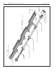
Figure 9a. Coupling Assembly
To assemble the coupling, hook the free end of the
coupling sleeve into the lanced clip. Place the wide end of
the tapered slide bar on the coupling so that it moves
toward the lanced clip. Insert the two tube ends into the
coupling. Be sure the tube ends are in line and are flush
against the stop pins inside the coupling.
Impact Block
Tighten
Loosen
When assembling coupling, the wide end of
the slide bar moves toward the lanced clip
Orient coupling so that the impact
block is above tube centerline.
C
L
Stainless Steel
Coupling
Slide Bar
Lanced Clip
C
L
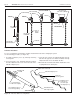
Figure 10. Tube Clamp Package
Position tube and
reflector hanger no
more than 4" (10 cm)
away from the burner
assembly.
Flat Washer
and Hex Nut
Tube Clamp
Carriage Bolt
Transition Tube
Burner Assembly
S-hook
Figure 11. Reflector Support Package
Reflector Support P/N 03050010
includes Support Strap, Wire Form, and (2) Screws.
For slip joint, loosen screws approx. 1/16" (2mm).
Reflector
Sheet metal
screw
Heating tube
Reflector
support strap
Wire form
Hammer-drive the slide bar until the coupling is secured
snugly to the tubes. Overdriving the slide bar will distort
the coupling or slide bar lip and will decrease the holding
capability of the coupling. Coupling should be tight when
the slide bar is ±2" (5 cm) from the end of the coupling.
See Figure 9a.
Use a 4 ft. level as indicated to establish pitch of
tubing and to ensure that tubes fit squarely at ends.
This in turn will insure the proper fit of couplings.
Figure 9b. Level Tubing