
Service manual


VANTAGE
®
EV INSTALLATION MANUAL ROBERTS-GORDONpg 10
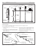
Section 7. Assembly Overview
Reflector End Cap
Punch out center section to accommodate
tube. Attach with U-Clips provided.
Standard Coupling
Coupling should be oriented with slide bar
on top.
LOOSE
SCREWS
TIGHT
SCREWS
Reflector Support Package
One support is required at
every reflector overlap. The
support closest to the burner
and every other support after
should have the screws
loosened approx. 1/16" (2 mm)
to allow for reflector slippage.
Tube and Reflector Hanger
with Clamp Package
Position this hanger no more
than 4" (10 cm) away from the
burner assembly. Install tube
clamp package as shown.
Suspend from S-Hook.
Burner Housing
(shown with tube gasket)
Must be installed with the
flame observation window
facing down.
Turbulator
Turbulator must be installed in the last standard section of
radiant tube. All VANTAGE EV burner cartons will include
the appropriate 10 ft. long turbulator assembly.
Heat Exchanger Tube
Supplied in 10 ft. (3 m) lengths.
Tube type as indicated. Also used
as manifold to connect the radiant
tube to the vacuum pump.
Transition Tube
Supplied in 10 ft. (3 m) lengths.
Transition tube is always the first
tube after the burner. Attach to burner
housing using the (4) split lock-washers,
(4) cap screws and tube gasket provided
in the burner package.
Reflectors
Alternate overlap as shown on
overview using amount indicated.
Minimum overlap is 9" (23 cm).
Tube and Reflector Hanger
Suspend system from these
hangers. Minimum one (1)
required per tube. Suspend
from S-Hook.
Vacuum Pump
(EP-200 model shown)
Every VANTAGE
EV system of
1-6 burners requires a vacuum
pump. Pump must be installed
with the proper discharge direction
and motor rotation. See Section 4
for design requirements.
Electronic Control Panel
(optional) Provides system management
and zone temperature control for the
VANTAGE® EV system.
®
®
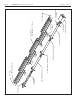
Figure 3. Assembly Overview
This section provides a general overview of component
placement in a
VANTAGE
®
EV system
. The location of
some components such as supports and couplings is
crucial to proper installation. Assemble the system
components as shown in Figures 4 thru 8.
Optional reflector configurations are shown in Figure 2.
Install appropriate suspension hardware, beam clamps,
chain or rod at predetermined locations. Adjustment of
chain length will provide uniform pitch.