
Service manual


VANTAGE
®
EV INSTALLATION MANUAL ROBERTS-GORDONpg 8
Part No. Description EV-80 EV-110 EV-140 EV-170 EV-200
VANTAGE
®
EV Burner Assembly (rate and fuel varies) 11111
02568200 Gasket (Burner to Transition Tube) 11111
151100NA Installation Manual 11111
91201708 Pipe Nipple (Black) 1/2 x 3-1/2 11111
94237914 Hex Head Cap Screw 5/16 - 18 x 7/8 44444
96411600 Split Lockwasher 44444
91412200 Flexible Gas Connector Assembly (1/2” NPT) 1 1 - - -
91412203 Flexible Gas Connector Assembly (3/4” NPT) - - 1 1 1
03051503 Turbulator Adapter 11111
03051504 Turbulator 2.5 ft. (76 cm) Section Piece 44444
Table 3. Contents of VANTAGE
®
EV Burner Carton
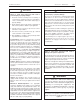
Section 6. Standard Parts List
nnnnnnnRequired Accessory Packagesnnnnnn
Model Tubing Length Standard Aluminized
EV-80 30' (9 m) CP30HRS CP30ALUM pg 11
EV-110 40' (12 m) CP40HRS CP40ALUM pg 12
EV-140 50' (15 m) CP30HRS + EXP20HRS CP30ALUM + EXP20ALUM pg 13
EV-170 60' (18 m) CP30HRS + EXP30HRS CP30ALUM + EXP30ALUM pg 14
EV-200 70' (21 m) CP40HRS + EXP30HRS CP40ALUM + EXP30ALUM pg 15
This section provides information about assembling
VANTAGE
®
EV systems. The heaters must be assembled
according to the following illustrations and tables in order
to ensure safe and proper operation.
VANTAGE
®
EV burner cartons contain the basic burner
unit, a Pipe Nipple and Flex Gas Line for gas connection,
and a 10 ft. Turbulator
The remaining heater components are shipped in one of
two ways:
1) Typically, tubes, reflectors, hangers, etc. are
pre-packaged at the factory. Components for VANTAGE
®
EV
systems up to 40 ft. (12 m) length are accommodated in
one carton that includes a 10 ft. (3 m) transition tube.
Longer VANTAGE
®
EV systems require two accessory
cartons. One carton will include a transition tube. (A few
Table 2. VANTAGE
®
EV Component Package Guide
minor components such as end caps may be duplicated.)
Required accessory packages for the various VANTAGE
®
EV models are shown in Table 2 below. Components
should be assembled as shown in Figures 9 thru 18.
2) In some cases, the VANTAGE
®
EV system may be
received with the accessory components non-
cartoned, or packaged for a specific installation. In
those cases, be sure to acquaint yourself with the
individual components shown in Figure 3. Also follow
carefully the appropriate diagram (Figures 4 thru 8) for
the heater you ordered. These indicate the quantity
and location of all necessary components.
Figures 4 through 8 show specific assembly details. Refer
to Section 9 for venting assembly, Section 10 for gas
piping assembly, and Section 11 for field wiring.
For Assembly
see page