® Vantage EV Installation, Operation & Service Manual EV-80 EV-110 EV-140 EV-170 EV-200 FOR YOUR SAFETY If you smell gas: 1. Open windows. 2. DO NOT try to light any appliance. 3. DO NOT use electrical switches. 4. DO NOT use any telephone in your building. 5. Leave the building. 6. Immediately call your local gas supplier after leaving the building. Follow the gas supplier’s instructions. 7. If you cannot reach your gas supplier, call the Fire Department.
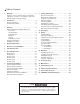
Table of Contents 1 2 Warnings . . . . . . . . . . . . . . . . . . . . . . . . . . . . . . . . 1 Read this section carefully. Improper installation, adjustment, operation or maintenance will result in death, injury or property damage. 9 General Requirements . . . . . . . . . . . . . . . . . . . . . .21 Manifold Pipe Requirements . . . . . . . . . . . . . . . . . .21 Venting the Vacuum Pump . . . . . . . . . . . . . . . . . . .21 EP-200 Installation . . . . . . . . . . . . . . . . . . . . . . . . .
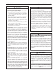
ROBERTS-GORDON SECTION WARNING FIRE OR EXPLOSION HAZARD Failure to follow these instructions will result in personal injury or property damage: 1. Read this manual carefully before installing or servicing this equipment. Improper installation, service or maintenance will result in death, injury or property damage. 2. Check clearances given on the outside of each burner to make sure the product is suitable for your application. 3.
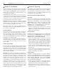
pg 2 VANTAGE® EV ROBERTS-GORDON I N S TA L L AT I O N M A N U A L Section 2. Introduction Roberts-Gordon pioneered low-intensity infrared heating systems in 1962 with the introduction of its revolutionary custom-engineered CORAYVAC® system. Now RobertsGordon offers over 35 years of infrared expertise in an economical vacuum system. VANTAGE ® EV model heaters are low-cost, noncondensing, field assembled vacuum-assisted heating systems that are easy to install and require only minimal maintenance.
ROBERTS-GORDON SECTION Electrical 3: PLANNING–CODES pg 3 Hazardous Locations WARNING WARNING Electrical Shock Hazard Heater must be installed and grounded according to national codes. Failure to follow these instructions will result in death or electrical shock. The heater must be electrically grounded in accordance with the following codes: United States: Refer to National Electrical Code, ANSI/NFPA-70 - latest revision.
pg 4 VANTAGE® EV ROBERTS-GORDON I N S TA L L AT I O N M A N U A L Critical Considerations Installation Procedure WARNING WARNING Several steps are involved in the installation of the heater. Do not attempt to operate the heater until all steps of the installation have been accomplished. Failure to follow these instructions will result in death, injury or property damage. Fire Hazard Some objects will catch fire or explode when placed close to heater.
ROBERTS-GORDON SECTION 4: pg 5 DESIGN REQUIREMENTS Section 4. Design Requirements EV-Series systems are typically shipped as burner packages and tube and accessory packages. The tube and accessory packages contain enough tube and reflector and hanging parts for one EV burner. Elbows, tees, tailpipe, vacuum pumps, controls, and any other parts must be purchased separately. See Figure 1 below for a general overview of a simple EV system.
6 VA N TAG E ® E V ROBERTS -GORDON I N S TA L L AT I O N M A N U A L Section 5. Clearances to Combustibles WARNING Fire Hazard Burn Hazard Some objects will catch fire or explode when placed close to heater. Keep all persons, especially children, away from heater. Keep all flammable objects, liquids and vapors the required safe distances away from heater. Failure to follow these instructions will result in death or injury. Do not touch any part of the heater. Heater is very hot.
ROBERTS-GORDON SECTION 5: pg 7 C L E A R A N C E S TO C O M BU S T I B L E S NOTE: All dimensions are in inches. A B C D Model A B C D EV-80 4 33 63 33 EV-110 4 33 63 33 EV-140 4 36 66 36 EV-170 4 39 73 39 EV-200 6 45 78 45 20 ft. downstream (all models) 4 17 40 17 Figure 2a. Standard Reflector A C D B C B D Figure 2c. 2 Side Reflectors B D C Figure 2d. 45° Tilt Reflector Model A B C D EV-80 4 4 69 51 EV-110 4 4 69 51 EV-140 4 4 71 56 EV-170 4 4 76 58 EV-200 6 4 82 64 20 ft.
pg 8 VANTAGE® EV ROBERTS-GORDON I N S TA L L AT I O N M A N U A L Section 6. Standard Parts List This section provides information about assembling VANTAGE® EV systems. The heaters must be assembled according to the following illustrations and tables in order to ensure safe and proper operation. VANTAGE® EV burner cartons contain the basic burner unit, a Pipe Nipple and Flex Gas Line for gas connection, and a 10 ft.
ROBERTS-GORDON Table 4. SECTION 6: pg 9 S TA N D A R D PA R T S L I S T Contents of Accessory Packages Extension Packages Core Packages Description 91409300 Tube, Hot Rolled Steel, 10 ft. 1 2 3 - - - - 1 2 3 4 - - - - 91409408 Tube, HT Aluminized, 10 ft. - - - - 1 2 3 - - - - 1 2 3 4 03051100 Transition Tube, Aluminized, 10 ft. 1 1 1 - 1 1 1 - - - - - - - - 03051600 Transition Tube, HT Aluminized, 10 ft.
pg 10 VANTAGE® EV ROBERTS-GORDON I N S TA L L AT I O N M A N U A L Section 7. Assembly Overview This section provides a general overview of component placement in a VANTAGE® EV system. The location of some components such as supports and couplings is crucial to proper installation. Assemble the system components as shown in Figures 4 thru 8. Optional reflector configurations are shown in Figure 2. Install appropriate suspension hardware, beam clamps, chain or rod at predetermined locations.
(2) Stainless Steel Couplings (1) 10 ft. Turbulator S-Hook (Typ.) TIGHT SCREWS Figure 4. Assembly of 30 ft (9 m) Radiant Tube Section - EV-80 (1) Tube Clamp Package A S S E M B LY OV E RV I E W (1) Burner Assembly (1) Gasket (3) Reflector Supports (4) U-Clips 7: (1) Transition Tube LOOSE SCREWS (4) Reflectors Overlap approx.
S-Hook (Typ.) Figure 5. Assembly of 40 ft (12 m) Radiant Tube Section - EV-110 LOOSE SCREWS (1) Burner Assembly (1) Tube Clamp Package (4) U-Clips I N S TA L L AT I O N M A N U A L (1) Gasket (5) Reflector Supports (6) Reflectors Overlap approx. 21" (53 cm) LOOSE SCREWS (1) Transition Tube TIGHT SCREWS (3) Stainless Steel Couplings (5) Tube and Reflector Hangers TIGHT SCREWS VANTAGE® EV (3) Heat Exchanger Tubes (1) 10 ft.
Figure 6. Assembly of 50 ft (15 m) Radiant Tube Section - EV-140 TIGHT SCREWS LOOSE SCREWS TIGHT SCREWS (1) Transition Tube LOOSE SCREWS (1) Tube Clamp Package A S S E M B LY OV E RV I E W (1) Burner Assembly (1) Gasket (6) Reflector Supports (4) U-Clips 7: (4) Stainless Steel Couplings TIGHT SCREWS LOOSE SCREWS (7) Reflectors Overlap approx. 13" (33 cm) SECTION (6) Tube and Reflector Hangers (4) Heat Exchanger Tubes S-Hook (Typ.) (1) 10 ft.
Figure 7. Assembly of 60 ft (18 m) Radiant Tube Section - EV-170 LOOSE SCREWS TIGHT SCREWS LOOSE SCREWS (1) Transition Tube TIGHT SCREWS (5) Stainless Steel Couplings (7) Tube and Reflector Hangers (5) Heat Exchanger Tubes TIGHT SCREWS LOOSE SCREWS (1) Burner Assembly (1) Tube Clamp Package (4) U-Clips I N S TA L L AT I O N M A N U A L (1) Gasket (7) Reflector Supports TIGHT SCREWS (8) Reflectors Overlap approx. 9" (23 cm) VANTAGE® EV S-Hook (Typ.) (1) 10 ft.
Figure 8. Assembly of 70 ft (21 m) Radiant Tube Section - EV-200 LOOSE SCREWS TIGHT SCREWS LOOSE SCREWS LOOSE SCREWS (1) Transition Tube LOOSE SCREWS (9) Reflector Supports (1) Tube Clamp Package (4) U-Clips A S S E M B LY OV E RV I E W (1) Burner Assembly (1) Gasket LOOSE SCREWS (10) Reflectors Overlap approx. 14" (36 cm) 7: (6) Stainless Steel Couplings TIGHT SCREWS TIGHT SCREWS (2) Reflector End Caps SECTION (8) Tube and Reflector Hangers (6) Heat Exchanger Tubes S-Hook (Typ.
pg 16 VANTAGE® EV I N S TA L L AT I O N M A N U A L ROBERTS-GORDON Section 8. Component Installation Hammer-drive the slide bar until the coupling is secured snugly to the tubes. Overdriving the slide bar will distort the coupling or slide bar lip and will decrease the holding capability of the coupling. Coupling should be tight when the slide bar is ±2" (5 cm) from the end of the coupling. See Figure 9a.
ROBERTS-GORDON 8: SECTION C O M P O N E N T I N S TA L L AT I O N pg 17 Elbow Package Installation (P/N 02718702) Elbow Package includes: (1) elbow, (1) coupling, (1) end cap, (1) reflector joint piece, and (1) package of U-Clips. Install elbow into radiant tube sequence where plans indicate a 90° bend. Install reflector joint piece using the following procedure: 1. Flatten reflector edge where joint piece matches. Put a mark on the reflector, directly over the tube center.
pg 18 VANTAGE® EV ROBERTS-GORDON I N S TA L L AT I O N M A N U A L Concrete Beam Bar Joist Clip Beam Clamp I-Beam Truss Screw Hook min. 3/8" (10mm) Locknut Washer Anchor I-Beam Washer 24" (60cm) minimum Wood Beam 12" (30 cm) minimum 3/16" or larger Chain S-Hook Turnbuckle (not included) Figure 15. Typical Suspension Details Turbulator Installation For ease of installation, the turbulator should be installed in the tube before hanging the system. Use the following procedure (see Figure 16): 1.
ROBERTS-GORDON SECTION 8: C O M P O N E N T I N S TA L L AT I O N pg 19 Side Extension Reflector Installation Optional Side Extension Reflectors may be installed on either side of the unit. Each 8 ft. section of Side Reflector should match a reflector and have identical overlap to adjacent reflectors. Provide slip joints in the same locations as the reflectors. Proceed as follows (see Figure 17): 1. Attach a reflector side extension support bracket to the tubes where needed.
pg 20 VANTAGE® EV ROBERTS-GORDON I N S TA L L AT I O N M A N U A L Reflector Cut Relief Notches for Tube and Reflector Hangers Tube A 2 ft. (60 cm) Aluminum Grille Shield P/N 01365900 Suspended Ceiling Frame Reflector Side Extension Figure 18. Installation of 2 ft. (60 cm) Decorative Aluminum Grille (optional) Decorative Grille Installation WARNING Cut Hazard Wear protective gloves when handling aluminum grille. Edges are sharp. Failure to follow these instructions will result in injury.
ROBERTS-GORDON SECTION 9: VENTING AND DUCTING pg 21 Section 9. Venting and Ducting General Requirements WARNING Carbon Monoxide Hazard Vented heaters must be vented outdoors. Vented heaters must be installed according to the installation manual. Failure to follow these instructions will result in death or injury. 6. Vent terminal opening must extend beyond any combustible overhang. 7. Install vent terminal at a height sufficient to prevent blockage by snow. 8.
pg 22 VANTAGE® EV Venting the Vacuum Pump (Continued) Venting from the pump may discharge either horizontally or vertically; corrosion resistant pipe is recommended. Vent lengths are allowed as follows: LENGTH ROBERTS-GORDON I N S TA L L AT I O N M A N U A L EP-200 PUMP EP-100 PUMP up to 10'(3m) 4"(10cm) vent/no elbows up to 25'(7.5m) 5"(12.5cm) vent/3 elbows 4"(10cm) vent/3 elbows up to 50'(15m) 6"(15cm) vent/3 elbows 5"(12.
ROBERTS-GORDON SECTION 25 feet and 3 elbows maximum 9: VENTING AND DUCTING 18" min.-40" max. Bird Screen (included w/ Pump Package) 4" Single Wall Pipe/Tube Approved Thimble (If Applicable) EP-100 Vacuum Pump Side Wall Venting pg 23 18" min.-40" max.
pg 24 VANTAGE® EV Chain Mounting (Optional, EP-100 Pump only) Chain (3/16" min) S-Hooks (optional, 3 required) ROBERTS-GORDON I N S TA L L AT I O N M A N U A L Wall Mounting Frame Parallel Wall Mounting Frame Perpendicular Min. 8" from wall Spring Lockwasher Washer (P/N 96411600) (P/N 95211600) Hex Head Screw 5/16"–18 x 3/4" (P/N 93413912) 11-5/16" 7" Hex Nut (P/N 92113900) 2 ft.
ROBERTS-GORDON SECTION Outside Combustion Air Supply IMPORTANT: If the building has a slight negative pressure or contaminants are present in the air, an outside combustion air supply to the heaters is strongly recommended. Some compounds such as halogenated hydrocarbons or other corrosive chemicals in the air can be drawn into the equipment and cause an accelerated rate of corrosion of some of the heater components. The use of such chemical compounds near the enclosure should be avoided.
pg 26 VANTAGE® EV ROBERTS-GORDON I N S TA L L AT I O N M A N U A L VERTICAL INSTALLATION Outside Air Terminal Roof 6" Flex Pipe 6" to 12" Long 4" Band Clamp Burner Assembly Sweeping Tee Connection HORIZONTAL INSTALLATION Wall 6" Band Clamp Burner Assembly Outside Air Terminal Sweeping 'Y' Connection 4" 4" Single Wall Pipe (Seal All Joints) Flex Pipe 6" to 12" Long 4" Figure 24.
ROBERTS-GORDON SECTION 10: GAS PIPING pg 27 Section 10. Gas Piping A 1/2" (EV-80 & -110) or 3/4" (EV-140, -170 & -200) gas supply connection at each burner location must be located and oriented as shown in Figure 25. To check system pressure, put a plugged 1/8" NPT tapping in the gas line at the connection to the burner furthest from the supply. Before connecting the burners to the supply system, verify that all high pressure testing of the gas piping has been completed.
pg 28 VANTAGE® EV ROBERTS-GORDON I N S TA L L AT I O N M A N U A L Section 11. Wiring WARNING Electrical Shock Hazard Disconnect electrical power before servicing. Failure to follow these instructions will result in death or electrical shock. VANTAGE ® EV systems may employ a solid-state Electronic Control Panel. In addition to providing system management, the control panel can also be used to provide individual zone temperature control for up to four zones.
ROBERTS-GORDON SECTION COM BLK N.O. BLK 11: WIRING pg 29 DOOR SWITCH THERMAL BUSHING TRANSFORMER BLUE 1 5 3 4 WHT 120VAC BLK AIR SWITCH BLUE GRN YEL BLUE GRN POWER BRN YEL VALVE SENSE GROUND YEL BLK IGNITION MODULE ELECTRODE GAS VALVE Figure 26. EV Burner Internal Wiring WARNING ATTENTION If any of the original wire as supplied with the heater must be replaced, it must be replaced with wiring material having a temperature rating of at least 105oC and 600 volts.
pg 30 VANTAGE® EV ROBERTS-GORDON I N S TA L L AT I O N M A N U A L Or an ge /Black llow Ye Re d n ow Br Black Yellow Hot (+) 115V Power Supply (Control Panel or Relay) Neutral (-) W h i te Magnetek TENV Motor: to reverse rotation, interchange black and red leads Bro wn/ White Bro wn /Wh ite Ground Screw Motor Junction Box Figure 28. Vacuum Pump Motor Wiring Motor Interlock (only on EP-200) See figure 29 for wiring details.
ROBERTS-GORDON SECTION 11: WIRING pg 31 WARNING Electrical Shock Hazard Disconnect electrical power before servicing. Failure to follow these instructions will result in death or electrical shock. Power Supply Gnd. Hot Neut. Vacuum Pump Zone 1 Burners Zone 2 Burners Hot Hot Hot Neut. Neut. Zone 3 Burners Zone 4 Burners Neut. Hot Neut. Hot Neut.
pg 32 VANTAGE® EV 3 Thermostats controlling Burner Zones 1-3 and optional SmartSet™ and Night Setback Thermostats. (Requires optional SmartSet™ panel). COM T1 T2 ROBERTS-GORDON I N S TA L L AT I O N M A N U A L T3 T4 MBR SCT NST MBR COM 4 Thermostats controlling Burner Zones 1-4. COM T1 T2 T3 T4 Night Setback Zone 1 Zone 3 SmartSet™ Zone 2 1 Thermostat controlling Burner Zones 1-4.
ROBERTS-GORDON SECTION 11: WIRING SPST Transformer Relay Night Set Back (Optional) R C W G Y Thermostat Black 1 3 2 4 COIL COIL Black Hot 120V-60 Hz Supply Circuit (Fused) 5 6 Neutral White Ground Red H H Vacuum Proving Switch N N Vacuum Pump Motor Figure 31.
pg 34 VANTAGE® EV ROBERTS-GORDON I N S TA L L AT I O N M A N U A L DPST Transformer Relay R DPST Transformer Relay C W G R C W G Y Zone 1 Thermostat Y Zone 2 Thermostat Purple 1 4 COIL 2 5 Red 3 1 6 4 Purple COIL Red 3 2 COIL 5 6 COIL Black Black Black Red/Yellow White 120V-60 Hz Supply Circuit (Fused) White Hot Neutral Ground H H Vacuum Proving Switch Red/Yellow Black N H N N Vacuum Pump Motor Figure 32.
ROBERTS-GORDON SECTION 12: O P E R AT I O N pg 35 Section 12. Operation WARNING Disconnect gas and electrical supplies before performing service or maintenance. Replace door before operating. Failure to follow these instructions will result in death, injury or property damage. Starting the System Checking the Gas Line 1. Open main valve and verify that no gas is flowing through the gas meter. 2. Purge the line if this was not done following pressure testing with air. 3.
pg 36 VANTAGE® EV ROBERTS-GORDON I N S TA L L AT I O N M A N U A L Setting the Vacuum 1. Set thermostats above room temperature. See that all burners are operating properly. Check the vacuum differential at all burners, then adjust the damper coupling to obtain approximately equal vacuum differential readings. Then adjust the pump inlet damper until vacuum differential readings are a minimum 0.5" to 0.6" w.c..
ROBERTS-GORDON SECTION 12: O P E R AT I O N pg 37 Sequence of Operation Burner Sequence of Operation Sequence of Operation (no control panel) 1. When sufficient vacuum differential (minimum 0.5" w.c.) is available at the burner, and the control system is supplying line voltage to the burner, the air sensing switch within the burner closes and energizes the direct spark ignition module. 1. Thermostat, on a call for heat, energizes the relay coil, closing the relay contacts. 2.
After a 45 pre-purge period, does the burner light? Yes Turn up thermostat. Does the pump turn on? No No Yes Yes Yes Repair or Replace switches as necessary. Replace main control board. (P/N 90437500) No No No Yes Yes Replace transformer. (P/N 90436900) Yes With the blue and yellow wires still removed, is the voltage at No the transformer black and white leads 120V? Reset dampers Reconnect transformer wires. Place a jumper wire across the pressure switch.
No Do all the burners ignite smoothly? No Does the pump shut down after a 45 second post-purge period? Yes Replace ignition module. (P/N 90434002K) Turn valve on. No Check thermostat wiring for shorts and replace thermostat if necessary. No Check thermostat wiring for shorts and replace thermostat if necessary. Yes Yes Replace pump relay. (P/N 90437900, Omron G4B112T1-US, or equivalent) No Replace/Correct wires. Check gas line stop cock. Contact gas company.
pg 40 VANTAGE EV ® I N S TA L L AT I O N M A N U A L Section 14. Maintenance WARNING Disconnect gas and electrical supplies before performing service or maintenance. Failure to follow these instructions will result in death, injury or property damage. For best perfor mance, the following maintenance procedures are recommended prior to each heating season.
ROBERTS-GORDON SECTION 15: pg 41 I L L U S T R AT E D PA R T S L I S T Section 15. Illustrated Parts List WARNING Use only genuine Roberts-Gordon replacement parts. Failure to follow these instructions will result in death, injury or property damage. 5 8 7 10 1 9 TOP VIEW 2 3 4 SIDE VIEW 6 11 10 Figure 34.
pg 42 VANTAGE EV ® I N S TA L L AT I O N M A N U A L Replacement Parts List (See Figure 34) Item Part Number Description 1 90427400 Electrode 02558501 Electrode Gasket 2 90436900 Transformer 3 90436701 Air Sensing Switch 4 90434004 DSI Module 5 90436800 Door Switch 6 91911700 Flue Collar 4" 7 03020100 Burner Cup Assembly 8 03090700T Manifold 9 90032500 Gas Valve (Natural Gas) 90032502 Gas Valve (LP Gas) 10 02553203 Mica Window Assembly 11 02568200 Tube Gasket ROBER
ROBERTS-GORDON SECTION 15: I L L U S T R AT E D PA R T S L I S T pg 43 Tubing and Related Accessories Plain Coupling P/N 01312700 45° Elbow, Aluminized P/N 01336101 Lined Coupling P/N 0131270 I Tube Clamp Package P/N 01318901 Damper Coupling P/N 01331900 Transition Tube, Aluminized, 10 ft. P/N 03051100 Tee, Coated P/N 0133022D Tee, Aluminized P/N 01330203 Transition Tube, Heat Treated Aluminized, 10 ft. P/N 03051600 Tube Plug P/N 01330800 Tube, Hot Rolled Steel, 10 ft.
pg 44 VANTAGE EV ® I N S TA L L AT I O N M A N U A L ROBERTS-GORDON Section 16. Engineering Specifications The total heating system supplied shall be design B. Heat Exchanger cer tified by the American Gas Association and the 1. Radiant tubing shall be 4" diameter, 16 gauge, Canadian Gas Association.
ROBERTS-GORDON SECTION 17: G E N E R A L S P E C I F I C AT I O N S pg 45 Section 17. General Specifications General Specifications for VANTAGE® EV heaters are as follows: Heat Exchanger Tubing 13.75" Reflector Turbulator 17.5" 9.5" Model EV-80 EV-110 EV-140 EV-170 EV-200 Rate 80,000 Btu/hr 110,000 Btu/hr 140,000 Btu/hr 170,000 Btu/hr 200,000 Btu/hr TOTAL LENGTH Min. Max.* 31' 9" 51' 9" 41' 9" 61' 9" 51' 9" 71' 9" 61' 9" 91' 9" 71' 9" 101' 9" SUGGESTED MINIMUM MOUNTING HT.
ROBERTS-GORDON SECTION 18: L I M I T E D WA R R A N T Y pg 47 Section 18. VANTAGE® EV Limited Warranty WARRANTY COVERAGE: Roberts-Gordon, Inc. (“Seller”) warrants that entire heating systems sold by it (individually a “System”) and any replacement parts which it sells relating to any System (“Parts”) shall be free from defects in workmanship and material for the time periods described as follows.