
Service manual

SECTION 6: PRESSURE SWITCH MOUNTING AND WIRING
11 o f 27
SECTION 6: PRESSURE SWITCH MOUNTING AND WIRING
6.1 Pressure Switch Installation
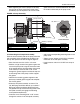
For connection to a pump, locate the two pressure
switch mounting holes on the pump frame. If replac-
ing an old pressure switch, you may need to drill two
holes in the pump frame (7/32" dia.
approximately 13/16" apart).
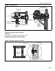
FIGURE 6: Pressure Switch Mounting Hole
Location
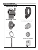
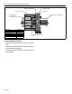
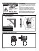
Using screws and locknuts included, mount the
switch to the pump frame. Thread the barbed fitting
into the threaded hole at the pump inlet. Cut the sili-
cone tube to the appropriate length to eliminate the
possibility of kinks and securely attach the hose to
the pressure switch and the barbed fitting.
FIGURE 7: Mounted Pressure Switch
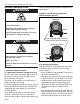
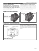
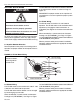
FIGURE 8: Wiring - Pump Pressure Switch ONLY
Pressure Switch
Mounting Holes
(located on both
sides of pump frame)
Barbed
Fitting
Silicone Hose
Pressure Switch
Ground Screw
Common Terminal
Normally Open Terminal
Connect the wire leads provided to terminals 1 and 2
labeled (C) Common and (NO) Normally Open. Refer
to the pressure switch kit installation instructions or
control panel installation instructions for connection to
controls.