
Service manual


SECTION 5: PUMP I NSTALLATION
9 of 27
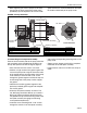
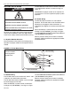
• While tightening the screws (torque to 132 in/lb)
that secure the pump scroll to the motor frame,
periodically spin the impeller to be sure that ade-
quete clearance is maintained between the impel-
ler blades and the body of the pump scroll.
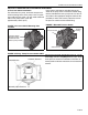
FIGURE 4: Pump Assembly
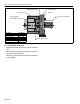
5.1.3 Attaching the Pump Inlet Assembly
From the scroll assembly side of the pump, orient the
inlet assembly so the threaded pipe coupling is on
the top. See partial end view on Page 9, Figure 4.
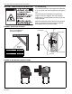
• Place flat washer on the 5/16" x 7/8" screw.
• Position a single section of the gasket against the
face of the pump scroll; align the clearance holes
of the gasket with the mounting holes of the pump
scroll. Loosely install one 5/16" x 7/8" screw
through the gasket segment and into the top cen-
ter mounting hole of the pump scroll to support
the gasket.
• Interlock the remaining gasket segment to the
previously installed gasket segment to complete
the circular gasket.
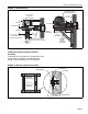
• Orient the inlet plate assembly as shown. The
1/8" NPT plug should face directly up, and the 1"
NPT plug should face directly downward. Care-
fully position the top center mou
nting notch of the
inlet plate assembly to engage the mounting
screw positioned previously.
• Install the seven remaining 5/16" x 7/8" screws
through the notches in the inlet plate assembly
• and into the corresponding mounting holes in the
pump scroll.
• Tighten screws (torque to 132 in/lb) to complete
installation of the inlet plate assembly.
• Install pressure switch in 1/8" NPT hole in top of
outlet.
Inlet Plate Assembly
Impeller
Pump Scroll
Gasket (2 pieces)
Partial End View
1" NPT
Rubber
Mounts
5/16 x 7/8" Screws (w/flat washers) - 16 Req'd.
1/8" NPT
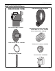
Description Part Number
Pump Scroll 01394400
Rubber Mounts 91906100
Impeller 01394602
Description Part Number
Inlet Plate Assembly Kit 01327400
Gaskets (2) 91406940
Inlet Plate 01327400
Accessory Bag (8 bolts, 8 flat washers) 01311702