EP-200 Series Pump Installation, Operation & Service Manual WARNING Improper installation, adjustment, alteration, service or maintenance can result in death, injury or property damage. Read the Installation, Operation and Service Manual thoroughly before installing or servicing this equipment. Installation must be done by a contractor qualified in the installation and service of gas-fired heating equipment or your gas supplier.
TABLE OF CONTENTS SECTION 1: Heating System Safety ............................1 1.1 Manpower Requirements ....................................1 1.2 Safety Labels and Their Placement ....................1 1.3 California Proposition 65 .....................................1 SECTION 2: Installer Responsibility............................3 2.1 Corrosive Chemicals...........................................3 2.2 National Standards and Applicable Codes .........3 SECTION 3: Unpacking the Pump ....................
TABLE OF FIGURES Figure 1: Label Placement ..............................................2 Figure 2: Major Component Descriptions........................5 Figure 3: Pump Discharge Orientation / Impeller Rotation Direction ..............................8 Figure 4: Pump Assembly ...............................................9 Figure 5: Motor Shaft Seal Assembly ............................10 Figure 6: Pressure Switch Mounting Hole Location .........................................................
SECTION 1: HEATING SYSTEM SAFETY SECTION 1: HEATING SYSTEM SAFETY Your Safety is Important to Us! This symbol is used throughout the manual to notify you of possible fire, electrical or burn hazards. Please pay special attention when reading and following the warnings in these sections. Installation, service and annual inspection of heater and pump must be done by a contractor qualified in the installation and service of gas-fired heating equipment. 1.
EP-200 SERIES PUMP INSTALLATION, OPERATION AND SERVICE MANUAL FIGURE 1: Label Placement Description Severe Injury Label Rating Plate Label Logo Label 2 of 27 Part Number 91012100 91010401 91017200
SECTION 2: INSTALLER RESPONSIBILITY SECTION 2: INSTALLER RESPONSIBILITY The installer is responsible for the following: • To install the pump and electrical supplies, in accordance with applicable specifications and codes. Roberts-Gordon recommends the installer contact a local building inspector or fire marshal for guidance. • To use the information given in a layout drawing and in the manual together with the cited codes and regulations to perform the installation.
EP-200 SERIES PUMP INSTALLATION, OPERATION AND SERVICE MANUAL SECTION 3: UNPACKING THE PUMP 3.1 Open Shipping Cartons WARNING Cut/Pinch Hazard Wear protective gear during installation, operation and service. Edges are sharp. Failure to follow these instructions can result in injury. Open cartons and remove packing inserts. Carefully remove pump components from the cartons. Lift assembly by gripping metal pump frame. Two people are required (weight 112 lb, 51 kg).
SECTION 4: MAJOR COMPONENTS SECTION 4: MAJOR COMPONENTS FIGURE 2: Major Component Descriptions EP-201 Pump Assembly - 01312001 EP-203 Pump Assembly - 01312002 Pump Scroll Assembly - 01394400 Inlet Plate Assembly - 01327400 Boot Replacement Package - 02771000 Flexible Boot 4.
EP-200 SERIES PUMP INSTALLATION, OPERATION AND SERVICE MANUAL 4.1 Standard Parts List Table 1: EP-201 Pump Package (P/N 02716305) Part No.
SECTION 4: MAJOR COMPONENTS Table 2: EP-203 Pump Package (P/N 02712034) Part No.
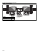
EP-200 SERIES PUMP INSTALLATION, OPERATION AND SERVICE MANUAL SECTION 5: PUMP INSTALLATION WARNING outlet must always be positioned at the bottom horizontal position. FIGURE 3: Pump Discharge Orientation / Impeller Rotation Direction Counterclockwise Rotation (Standard) Severe Injury Hazard Secure pump to tube. Hang pump with materials with a minimum working load of 750 lbs (340 kg). OUTLET Failure to follow these instructions can result in death, injury or property damage.
SECTION 5: PUMP INSTALLATION • While tightening the screws (torque to 132 in/lb) that secure the pump scroll to the motor frame, periodically spin the impeller to be sure that ade- quete clearance is maintained between the impeller blades and the body of the pump scroll. FIGURE 4: Pump Assembly 5/16 x 7/8" Screws (w/flat washers) - 16 Req'd.
EP-200 SERIES PUMP INSTALLATION, OPERATION AND SERVICE MANUAL FIGURE 5: Motor Shaft Seal Assembly Motor Shaft Seal Pump Frame Impeller EP-201 Motor or EP-203 Motor Description EP-201 Motor EP-203 Motor Motor Shaft Seal Pump Scroll Impeller Inlet Plate Assembly Part Number 90604500 90604501 02757500 01394400 01394602 01327400 Inlet Plate Assembly Motor Shaft Hub 5.1.4 Install Motor Shaft Seal • Separate the motor shaft seal at the pre-cut score line.
SECTION 6: PRESSURE SWITCH MOUNTING AND WIRING SECTION 6: PRESSURE SWITCH MOUNTING AND WIRING 6.1 Pressure Switch Installation Using screws and locknuts included, mount the switch to the pump frame. Thread the barbed fitting For connection to a pump, locate the two pressure switch mounting holes on the pump frame. If replac- into the threaded hole at the pump inlet.
EP-200 SERIES PUMP INSTALLATION, OPERATION AND SERVICE MANUAL SECTION 7: PUMP MOUNTING INSTRUCTIONS 7.1 Wall Mounting The standard method of mounting the EP-200 pump is on an outside wall and venting directly through the wall. The pump may be mounted by using mounting angles as shown in Figure 9. The two mounting angles form a mounting platform to which the pump will be attached. Attach the mounting frame to the wall using anchors.
SECTION 7: PUMP MOUNTING INSTRUCTIONS FIGURE 11: Wall Mounting 4.5" X 8" (114 x 203mm) Flexible Boot with Silicone Rubber Ring 5/8" (16 mm) Diameter Mounting Holes 5-6" (127-152mm) 7" (178 mm) 3.9" (99 mm) 7" (178 mm) 4.5" x 8" (114 x 203mm) Flexible Boot with Silicone Rubber Ring 10" (254mm) 8.5" (216mm) 3.25" (83mm) 5-6" (127-152 mm) Thimble (if applicable) Silicone Rubber Ring (Install on 4" (102 mm) Tube) 4" (102 mm) Tube 11.5" (292mm) 7"- 8" (178-203mm) Mounting Angle Assembly (Standard) 7.
EP-200 SERIES PUMP INSTALLATION, OPERATION AND SERVICE MANUAL SECTION 8: MOTOR WIRING The EP-200 series motor must be wired for clockwise or counterclockwise rotation as shown on Page 14, Figure 13. DANGER IMPORTANT: Improper rotation of the impeller will not produce the vacuum required for proper system operation. 8.2 EP-201 Wiring Electrical Shock Hazard Disconnect electric before service. Appliance must be properly grounded.
SECTION 8: MOTOR WIRING FIGURE 14: EP-203 Motor Wiring Note: Interchange any two line leads to reverse rotation.
EP-200 SERIES PUMP INSTALLATION, OPERATION AND SERVICE MANUAL SECTION 9: VENTING WARNING Carbon Monoxide Hazard Pump must be vented to the outside. Heaters must be installed according to the installation manual. Failure to follow these instructions can result in death or injury. WARNING accordance with all local and national codes. 9.2 Venting the Pump • The exhaust connection from the pump is 4.5" (11 cm) diameter.
SECTION 9: VENTING • Vent must terminate at least 3' (1 m) above any forced air inlet located within 10' (3 m). • Vent terminal opening must extend beyond any combustible overhang. • Vent must terminate at least 4' (1.2 m) below 4' (1.2 m) horizontally from or 12" (30 cm) above any door, window or gravity air inlet into building. • Install vent terminal at a height sufficient to prevent blockage by snow.
EP-200 SERIES PUMP INSTALLATION, OPERATION AND SERVICE MANUAL 9.4 Vertical Venting Condensation will form in the vent pipe. Insulation and additional sealing measures may be required. Length of flue pipe is equal to total of vertical and horizontal length.
SECTION 9: VENTING FIGURE 18: Condensate Tee - Discharge Side 9.5 Condensate Trap and Condensate Tee The condensate trap assembly (optional) (P/N Step 2: Total condensate 01327001), should be installed on the inlet side of the EP-200 Series pump assembly, See Page 18, Figure Determine the total condensate (gal/h) using the follow calculation: 17. It is possible to eliminate the condensate trap assembly on the pump if the one-inch threaded hole is plugged.
EP-200 SERIES PUMP INSTALLATION, OPERATION AND SERVICE MANUAL Step 3: Choose the condensate neutralization tube Choose the condensate neutralization tube which is closest to and higher than the calculated gal/h value. For this example, the total condensate is 1.8 (gal/h), the condensate neutralization tube which is closest to and higher than the calculated gal/h value is P/N 01327002.
SECTION 10: SERVICING INSTRUCTIONS SECTION 10: SERVICING INSTRUCTIONS WARNING DANGER Electrical Shock Hazard Disconnect electric before service. Explosion Hazard Turn off gas supply to heater before service. Heater and pump must be connected to a properly grounded electrical source. Burn Hazard Allow heater and pump to cool before service. Cut/Pinch Hazard Wear protective gear during installation, operation and service. Tubing may still be hot Edges are sharp. after operation.
EP-200 SERIES PUMP INSTALLATION, OPERATION AND SERVICE MANUAL 3. The motor can now be removed, if necessary, by loosening the attachment hardware. 4. Re-assembly of motor/impeller combination require proper alignment. Make sure the impeller has a 1/4" (6 mm) clearance off the inside wall of the scroll. Verify proper motor alignment and free rotation. 5. The two) impeller set screws should be removed and reinstalled with a drop of thread locking sealant and remain unseated during initial reassembly. 6.
SECTION 10: SERVICING INSTRUCTIONS 10.3 Maintenance Checklist Installation Code and Annual Inspections: All installation and service of ROBERTS GORDON® equipment must be performed by a contractor qualified in the installation and service of equipment sold and supplied by Roberts-Gordon LLC and conform to all requirements set forth in the ROBERTS GORDON® manuals and all applicable governmental authorities pertaining to the installation, service, operation and labeling of the equipment.
EP-200 SERIES PUMP INSTALLATION, OPERATION AND SERVICE MANUAL SECTION 11: REPLACEMENT PARTS AND ACCESSORIES WARNING DANGER Electrical Shock Hazard Explosion Hazard Carbon Monoxide Hazard Fire Hazard Use only genuine ROBERTS GORDON® replacement parts per this installation, operation and service manual. Failure to follow these instructions can result in death, electric shock, injury or property damage. Pump Scroll Band Clamp Pump Boot 4" Inlet Plate Assembly 11.
SECTION 11: REPLACEMENT PARTS AND ACCESSORIES Description 4" Aluminized Cross 4" Coated Cross 4" (10 cm) Band Clamp 6" (15 cm) Band Clamp Part Number 01330903 0133092D 91901300 91913703 Description 6" Tube Hanger 4" Drain Cap 6" Drain Cap Condensate Trap Part Number 91240010 02718851 02718852 01327001 25 of 27
EP-200 SERIES PUMP INSTALLATION, OPERATION AND SERVICE MANUAL SECTION 12: SPECIFICATIONS Pump Dimensional Data (in.) Model A B C EP-201 17.75 17 20.25 EP-203 D E F G 3.25 10 4.5 4.5 G A E D B C F dia. Pump Specifications Model EP-201 EP-203 Horsepower (Hp) 3/4 3/4 Phase (Ø) 1 3 Hertz (Hz) 60 60 Voltage (V) 115/230 208 -230 / 460 Full Load Amp (A) 6.6/3.3 2.4 - 2.2 / 1.1 R.P.M.
SECTION 13: THE ROBERTS GORDON® EP-200 SERIES PUMP WARRANTY SECTION 13: THE ROBERTS GORDON® EP-200 SERIES PUMP WARRANTY ROBERTS-GORDON LLC WILL PAY FOR: Within 36 months from date of purchase by buyer or 42 months from date of shipment by Roberts-Gordon LLC (whichever occurs first), replacement parts will be provided free of charge for any part of the product which fails due to a manufacturing or material defect. Roberts-Gordon LLC will require the part in question to be returned to the factory.