
Service manual


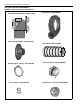

TABLE OF FIGURES
Figure 1: Major Component Descriptions........................4
Figure 2: Pump Discharge Orientation............................6
Figure 3: Pump Assembly ...............................................7
Figure 4: Damper Assembly............................................8
Figure 5: Motor Shaft Seal Installation ............................9
Figure 6: EP-100 Mounting - Chain Suspension ...........10
Figure 7: Wall Bracket Assembly................................... 11
Figure 8: Wall Mounting Angle Assembly .....................12
Figure 9: Wall Mounting ................................................12
Figure 10: Optional Platform Assembly Mounting .........13
Figure 11: EP-100 Contactor Wiring Diagram...............14
Figure 12: Pressure Switch Mounting Holes .................15
Figure 13: Pressure Switch Mounting............................15
Figure 14: Pump Pressure Switch ................................15
Figure 15: Horizontal Venting ........................................17
Figure 16: Vertical Venting ............................................17