
Service manual

EP-100 PUMP INSTALLATION, OPERATION AND SERVICE MANUAL
8
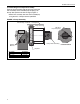
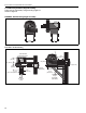
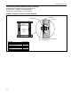
5.1.4 Damper Assembly
The pump is equipped with a damper assembly
which is used as a means of setting the system
vacuum. See the appropriate Installation, Operation
and Service Manual for additional vacuum setting
information.
1. When the pump is installed, be certain to lock
the damper in the full open position with the
(1/4"- 20) Hex Head bolt. See Figure 4.
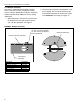
2. The pump inlet assembly is provided with a 1/8"
N.P.T. tapping. This is to be located at the top
and used for connection of the pressure switch
(P/N 90430600K). See Page 15, Figure 13.
FIGURE 4: Damper Assembly
Damper Support Assembly
1/4"-20 x 1/2 Hex Head Bolt
1/4" Ext. Tooth Lock Washer
5/16" Flat Washer
Inlet Flange
Assembly
Restricter Assembly
Description Part Number
Damper Support Assembly 01329500
Inlet Flange Assembly 02724200
1/4"-20 x 1/2" Hex Head Bolt 93413008
1/4" Ext. Tooth Lock Washer 96211500
5/16" Flat Washer 95211600
Restrictor Assembly 01327500