
Service manual


SECTION 10: SERVICING INSTRUCTIONS
25 of 29
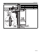
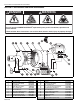
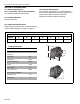
6. The motor can now be detached, if necessary,
by removing the attachment hardware.
7. Re-assembly of motor/impeller combination
requires proper alignment. Make sure the
impeller has a 1/4" (6 mm) clearance off the
inside wall of the scroll. Be certain of the proper
motor alignment and free rotation.
8. The two impeller set screws should be
reinstalled with a drop of thread locking sealant
and remain unseated during initial re-assembly.
9. Slide the impeller onto the motor shaft end.
10.Seat the two impeller set screws. Torque to 100
in/lbs.
11. Re-attach the scroll and inlet. Secure with all six
nuts. Torque to 150 in/lbs.
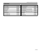
10.3 Maintenance Checklist
Installation Code and Annual Inspections:
All installation and service of ROBERTS GORDON
®
equipment must be performed by a contractor
qualified in the installation and service of equipment
sold and supplied by Roberts-Gordon LLC and
conform to all requirements set forth in the
ROBERTS GORDON
®
manuals and all applicable
governmental authorities pertaining to the
installation, service,
operation and labeling of the equipment.To help
facilitate optimum performance and safety, Roberts-
Gordon LLC recommends that a qualified contractor
conduct, at a minimum, annual inspections of your
ROBERTS GORDON
®
equipment and perform
service where necessary, using only replacement
parts sold and supplied by Roberts-Gordon LLC.
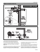
System Tubing and
Vent Pipe
Venting must be intact. Using a flashlight, look for obstructions, cracks on the
pipe, gaps in the sealed areas or corrosion.
The area must be free of dirt and dust or blockage.
Remove any carbon deposits or scale using a wire brush.
Replace pipe if there are any holes due to corrosion. Seal any gaps in venting
to prevent condensate leakage.
Pump Scroll, Impeller and
Motor
Compressed air or a vacuum cleaner may be used to clean dust and dirt.
Check for corrosion, if any parts have corroded through, replace as neces-
sary.
Ensure all hex nuts are tight for proper seal.
Suspension Points Make sure the pump is hanging securely.
Look for signs of wear on the mounting angles, wall mounting points or ceiling
mounting points.
Pump Boot Inspect pump boot at pump inlet and outlet for cracking or deterioration.
Replace if cracks are found.
Ensure band clamps are tight at all connection points.
Condensate Trap, Drain
Cap
Check connection of tee to drain cap and between tee and condensate trap.
Seal connections between tee and drain cap to prevent condensate leakage.
Screw condensate trap tightly into drain cap to prevent leakage.
Condensate trap should be filled with water.
Pressure Switch Ensure that wiring is intact. Check silicone hose for cracks.
Ensure secure connection between pressure switch and barbed fitting.
Safety Labels Product safety signs or labels should be replaced by the product user when
they are no longer legible. Please contact Roberts-Gordon LLC or your
ROBERTS GORDON
®
independent distributor to obtain replacement signs or
labels. See Page 2, Figure 1.