
Service manual

SECTION 9: VENTING
21 of 29
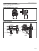
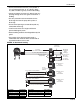
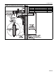
FIGURE 18: Condensate Check Valve
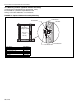
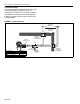
FIGURE 19: Condensate Tee - Discharge Side
9.6 Condensate Trap and Condensate Tee
The condensate trap assembly (optional) (P/N
01327001), should be installed on the inlet side of
the EP-200 Series pump assembly, See Page 21,
Figure 18.
It is possible to eliminate the condensate trap assem-
bly on the pump if the one-inch threaded hole is
plugged. This arrangement will permit drainage of
condensate through the pump and outside via hori-
zontal (pitched) discharge line.
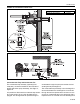
The condensate trap assembly in the discharge line
can be eliminated if the discharge line is horizontal
through the wall and pitched down at least one inch
per foot. A condensate trap on the discharge side is
required if there is a vertical rise in the discharge line.
Description Part Number
Condensate Valve Assembly 01327001