
Service manual

SECTION 8: MOTOR WIRING
17 of 29
SECTION 8: MOTOR WIRING
All wiring must comply with current wiring regulations
and any local regulations which may apply. Always
switch off the supply and disconnect before servicing.
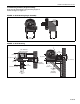
8.1 Impeller Rotation Direction
Prior to operation of the pump in the heating system,
operation and proper rotation of the impeller must be
verified. See impeller rotation direction arrow label on
the pump scroll for the correct rotation direction.
The motor must be wired for clockwise or
counterclockwise rotation.
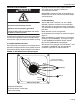
IMPORTANT: Improper rotation of the impeller can
produce only half of the vacuum required for proper
system operation.
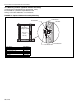
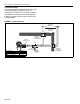
8.2 EP-100 Wiring
The EP-100 motor is wired for 1 Ø, 115 V, 60 Hz
operation. However, the motor can be rewired for
230 V operation by changing the motor connections
as indicated by the diagram on the motor connection
box cover.
Motor operation can be changed from
counterclockwise to clockwise as shown on Page 8,
Figure 3.
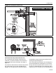
When controlled by a system control, use contactor
package 17A (P/N 10050011).
See Page 17, Figure
15. See ROBERTS GORDON
®
System Control
Manual (P/N 10091601NA) wiring details.
Wire the pressure switch per the CORAYVAC
®
(P/N
127102NA) or VANTAGE
®
NP (P/N 152101NA)
Installation, Operation and Service Manual.
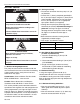
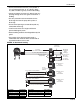
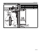
FIGURE 15: EP-100 Contactor Wiring Diagram
DANGER
Electrical Shock Hazard
Disconnect electric before service.
Appliance must be properly grounded.
Failure to follow these instructions can result
in death or electrical shock.
Ground
Screw
Black
Orange
Brown
Red
Yellow
White
Yellow/Black
115 V Power Supply
(Control Panel or Relay)
Neutral (-)
Motor Junction Box
Hot (+)
Magnetek TENV Motor:
To reverse rotation, interchange
black and red leads.