
Service manual


CTH2-SERIES INSTALLATION, OPERATION AND SERVICE MANUAL
46
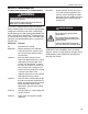
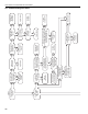
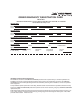
12.2 Troubleshooting Flow Chart
Replace igniter.
Is the resistance
through the igniter
50-400W?
Check wire
connections.
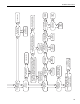
Check voltage at
igniter connection.
Is it 120V during
the ignition period?
Check thermostat
and wiring. Is the
power supply to
unit 120V?
Find the source of
the electrical
problem.
Is the inlet or
outlet of the unit
obstructed?
Remove
obstruction.
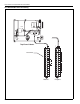
Check wiring and
connection diagram.
Is blower side
door in place?
Replace door.
Check wiring and hose
connection to pressure
switch. Are they OK?
Is the voltage between
the blue and orange
transformer leads 24V?
Is the voltage
between the black and
white transformer
leads 120V?
Remove door. Is
voltage at door
switch 120V?
Check wiring and
diagram.
Replace wiring
and/or hose
connections.
Replace
transformer.
Depress switch.
Does blower
come on?
Check voltage to
motor. Is it 120V?
Is the blower
obstructed?
Replace blower.
Within 30 seconds of power up,
place jumper between both yellow
wires at pressure switch.
Does the igniter glow red?
Replace
SmartValve
®
II
Check door fit;
if damaged,
replace door.
Replace switch.
Remove
obstruction.
Replace pressure
switch.
YES
Inspect igniter carefully.
Hairline cracks may
not be apparent.
Is the igniter damaged?
Does the igniter
warm up and
glow red?
Turn on thermostat.
Does blower
turn on?
YES
NO
NO
YES
NO
YES
NO
NO
NO
YES
NO
NO
YES YES YES
NO
YES
NO NO
YES
YES
NO YES
NO
YES
NO
NO
YES
NO
START