
Service manual

SECTION 10: WIRING
39
SECTION 10: WIRING
Heaters can be controlled using several methods.
Normally thermostats are used to control the heaters
but they can also be controlled by an Energy
Management System. Section 10.1 below illustrates
the connection for heaters controlled by a line voltage
thermostat. NOTE: In order to use line voltage ther-
mostats, the low voltage terminal located at the back
of each burner must be connected as shown in the
detail. For a single heater on a low voltage thermo-
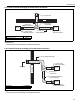
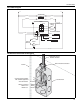
stat, See Section 10.2 below. To control multiple
heaters on one low voltage thermostat, See Page 40,
Section 10.3. NOTE: In order to control multiple heat-
ers on one low voltage thermostat, the low voltage
terminals on each heater must be connected as
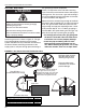
shown in detail. Heaters must be grounded in accor-
dance with applicable codes: United States: refer to
National Electrical Code
®
ANSI/NFPA 70 - latest revi-
sion; Canada: refer to Canadian Electrical Code CSA
C22.1 Part I - latest revision.
If any of the original internal wiring must be replaced,
it must be replaced with wiring materials having a
temperature rating of at least 105° C and 600 V.
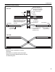
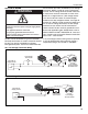
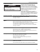
10.1 Line Voltage Thermostat Wiring
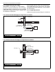
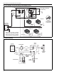
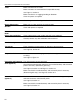
10.2 Low Voltage Thermostat with One Burner
WARNING
Electrical Shock Hazard
Disconnect electrical power and gas supply before
servicing.
This appliance must be connected
to a properly grounded electrical source.
Failure to
follow these instructions can result in
death or electrical shock.
Line Voltage
Thermostat
Gnd. Gnd.
120 V-60 Hz
Supply Circuit
HN HN
Gnd.
L1
L2
T
Low Voltage
Terminal Detail
On All Burners
Gnd.
120 V-60 Hz
Supply Circuit
HN
Gnd.
L1
L2
Low Voltage
Terminal Detail
Low Voltage
Thermostat
T