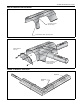
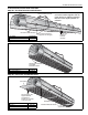
SECTION 7: OPTIONAL HEATER ACCESSORIES Step 7.2.4 Reflector Joint Installation Cut away contour with tin snips. Punch/drill six 3/32" (2 mm) holes. Step 7.2.5 Reflector Joint Detail Install reflector end cap. Attach reflector joint with six #8 sheet metal screws.
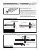
CTH2-SERIES INSTALLATION, OPERATION AND SERVICE MANUAL 7.3 Reflector Side Extension Step 7.3.1 Bracket Installation Tube Reflector Tube and Reflector Hanger Reflector Support Reflector Side Extension Bracket (2 per reflector) Use additional supports in high air movement applications. Description Reflector Side Extension Package Reflector Side Extension Retainer Clips Sheet Metal Screws Order Separately Reflector Side Extension Part Number 02712700 01368000 02751200 94118106 01329910 Step 7.3.
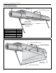
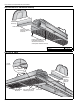
SECTION 7: OPTIONAL HEATER ACCESSORIES 7.4 Lower Clearance Shield Installation Step 7.4.1 Shield Support Strap Assembly Reflector 17.1" (434 mm) 12" (300 mm) Align Pilot Holes Lower Clearance Shield Locknuts Washers Screws Description Lower Clearance Shield Package Shield Support Strap Lower Clearance Shield 8' Locknut #8 Flat Washer #8 Screw #8 x 3/8" Part Number 01397501 01397500 02793000 92311400 95310800 93511406 7.5 Two-Foot Decorative Grille Installation Step 7.5.
CTH2-SERIES INSTALLATION, OPERATION AND SERVICE MANUAL Step 7.5.2 Frame Shield Installation Shield Description Deco Grille Shield Part Number 01365900 Step 7.5.3 Reflector Side Extension Installation for Decorative Grilles NOTE: If the Decorative Grille system is to be installed in an area with considerable air movement, it is recommended that one #8 x 3/8 (3.9 x 9.5 mm) sheet metal screw be installed per reflector extension to prevent it from blowing over.
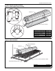
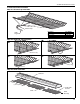
SECTION 7: OPTIONAL HEATER ACCESSORIES 7.6 One-Foot Decorative Grille Installation Step 7.6.1 One-Foot Decorative Grille Bracket #8 Sheet Metal Screws Decorative Grille Bracket Description Bracket Part Number 01363003 In order to maintain reflector shape, do not fasten brackets together. Do not fasten bracket to adjoining reflectors. Maintain same slipjoint position as reflectors. Cut relief notches for supports and hangers. 2" (51 mm) Minimum Bracket Overlap Step 7.6.
CTH2-SERIES INSTALLATION, OPERATION AND SERVICE MANUAL Step 7.6.4 End Piece and Reflector End Cap Reflector End Cap End Piece Insert end piece between grille and brackets. Fasten end piece to brackets using two #8 sheet metal screws and replace reflector end cap. Description End Piece Part Number 01365901 Step 7.6.5 90° Elbow Inside Corner Grille Brackets Joint Piece Insert End Piece between grille and brackets. Decorative Grille Brackets 30 Cut grille bracket at reflector joint piece.
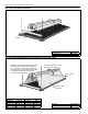
SECTION 7: OPTIONAL HEATER ACCESSORIES 7.7 Protective Grille Installation Step 7.7.1 Silicone Cap Installation Silicone Cap Description Grille Section Grille End Cap Silicone Cap Grille Finger Part Number 08050001 08050002 91915951-6P Step 7.7.2 Grille End Cap Installation B A Grille Grille End Cap C D Bend up 90° Pull outward Step 7.7.
CTH2-SERIES INSTALLATION, OPERATION AND SERVICE MANUAL SECTION 8: VENTING WARNING Carbon Monoxide Hazard Heaters installed unvented must be interlocked with sufficient building exhaust. Secure all joints with #8 x 3/8 sheet metal screws. Seal all joints with high temperature silicone sealant. Heaters must be installed according to the installation manual. 8.1.1 United States Requirements Vent must terminate at least 3' (.9 m) above any forced air inlet located within 10' (3.1 m).
SECTION 8: VENTING 8.6 Length Requirements The maximum vent length allowed is 45' (13.7 m). The maximum outside air supply duct length allowed is 45' (13.7 m). The total vent length, plus outside air duct length, plus any extensions to minimum heat exchanger lengths, cannot exceed 65' (19.8 m). 8.5 Unvented Operation Tube Termination Turndown type vent terminal with a screen must be installed at the exhaust end of the tube. Vent terminal design shall not incorporate backdraft flap.
CTH2-SERIES INSTALLATION, OPERATION AND SERVICE MANUAL 8.
SECTION 8: VENTING 8.10 Common Vertical Venting Type "B" vent cap (7" or 8") may be used. (These are not available from Roberts-Gordon.) Type "B" Vent Pipe SIDE VIEW Roof Flashing 18" (46 cm) Min. Roof Vent Adapter The last section of vent pipe passing through the roof or wall may be Type "B" vent pipe. All other vent materials in the building must be single wall vent pipe.
CTH2-SERIES INSTALLATION, OPERATION AND SERVICE MANUAL 8.11 Outside Combustion Air Supply IMPORTANT: If the building has a slight negative pressure or corrosive contaminants, such as halogenated hydrocarbons, are present in the air, an outside combustion air supply to the heater is required. Seal all combustion air pipe joints. The air supply duct may have to be insulated to prevent condensation on the outer surface. The outside air terminal must not be more than 1' (31 cm) above the vent terminal. 8.11.
SECTION 8: VENTING 8.11.4 Vertical Outside Air Supply for Double Heater Installation Vent Cap Roof 6" (15 cm) Single Wall Pipe Flex Hose (Recommended) Burner Band Clamp (Recommended) Description Vent Cap 6" (15 cm) Sweeping 'T' Connection Burner Flex Hose (Recommended) 4" (10 cm) Single Wall Pipe Part Number 90502302 Requirements: • Heaters must be controlled by a common thermostat. 8.11.
CTH2-SERIES INSTALLATION, OPERATION AND SERVICE MANUAL the gas piping has been completed. SECTION 9: GAS PIPING WARNING There is an expansion of the tube with each firing cycle. This will cause the burner to move with respect to the gas line. This can cause a gas leak resulting in an unsafe condition if the gas connection is not made in strict accordance with Figure 21. Fire Hazard Tighten gas hose fittings to connect gas supply according to Figure 20. Gas hose can crack when twisted.
SECTION 10: WIRING SECTION 10: WIRING WARNING Electrical Shock Hazard Disconnect electrical power and gas supply before servicing. This appliance must be connected to a properly grounded electrical source. Failure to follow these instructions can result in death or electrical shock. Heaters can be controlled using several methods. Normally thermostats are used to control the heaters but they can also be controlled by an Energy Management System. Section 10.
CTH2-SERIES INSTALLATION, OPERATION AND SERVICE MANUAL 10.3 Low Voltage Thermostat Wiring with Multiple Burners FRONT VIEW Transformer Relay 1 R 3 2 4 Black BACK VIEW COIL 5 Low Voltage Thermostat (P/N 90425100) C 6 COIL W G Y Purple Black White Burner 1 Red 120V-60Hz supply circuit Burner 2 Gnd. H Gnd. N H N L1 L2 Burner 3 Gnd. When using 1-2 burners, use SPDT Transformer Relay (P/N 90417600). When using 3-4 burners, use DPDT Transformer Relay (P/N 90436300). Burner 4 Gnd.
SECTION 10: WIRING 10.5 Ladder Diagram L2 L1 TRANSFORMER WHITE BLACK ORANGE BLUE VALVE WHITE TO THERMOSTAT PRESSURE SWITCH YELLOW YELLOW PURPLE HOT SURFACE IGNITER WHITE WHITE WHITE BLACK DOOR SWITCH GREY FLAME SENSOR MOTOR WHITE BLACK 10.6 Electrical Connection to the Burner Electrical Cord or Flexible Conduit BX or Romex Connector Burner Connect wires together with suitable approved wire connectors.
CTH2-SERIES INSTALLATION, OPERATION AND SERVICE MANUAL SECTION 11: OPERATION AND MAINTENANCE This heater is equipped with a hot-surface ignition system. 11.3 To Start Heater 11.1 Sequence of Operation 1. Turn the thermostat up. When the thermostat calls for heat, the SmartValve® II will energize. After a short period, power is supplied to the blower motor. Turn ON main gas valve. 2. When the motor approaches nominal running RPM, the pressure switch closes and signals the ignition module/SmartValve® II.
SECTION 11: OPERATION AND MAINTENANCE 11.5 Maintenance Checklist WARNING Turn off gas and electrical supplies before performing service or maintenance. Failure to follow these instructions can result in death, injury or property damage.
CTH2-SERIES INSTALLATION, OPERATION AND SERVICE MANUAL Tubes Make sure there are no cracks. Make sure tubes are connected and suspended securely. See Page 11, Section 6. Make sure there is no sagging, bending or distortion. Clean or replace as required. Gas Line Check for gas leaks. See Page 38, Section 9. Burner Observation Window Make sure it is clean and free of cracks or holes. Blower Scroll, Wheel and Motor Compressed air or a vacuum cleaner may be used to clean dust and dirt.
SECTION 12: TROUBLESHOOTING SECTION 12: TROUBLESHOOTING 12.1 Honeywell SmartValve® II Troubleshooting WARNING Turn off gas and electrical supplies before performing service or maintenance. Failure to follow these instructions can result in death, injury or property damage. This heater is supplied with the Honeywell SmartValve® II control system. This system is equipped with a diagnostic function that will assist in performing troubleshooting.
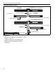
46 Does the igniter warm up and glow red? YES Turn on thermostat. Does blower turn on? START NO Check voltage at igniter connection. Is it 120V during the ignition period? Inspect igniter carefully. Hairline cracks may not be apparent. Is the igniter damaged? NO Is the voltage between the black and white transformer leads 120V? NO Is the voltage between the blue and orange transformer leads 24V? Remove obstruction. NO YES YES Check wiring and hose connection to pressure NO switch.
Were the gas lines purged of air? NO purge gas line. NO NO YES NO NO Repair/ correct wiring. Repair/ correct wiring. Is the wiring at the YES SmartValve® II OK? Adjust to proper pressure. See Section 12.3. NO YES Replace wires. Repair/ correct wiring. NO Replace flame sensor. NO Is the flame sensor dirty? YES YES Clean flame sensor. Repair/ Replace. Check for proper orifice. Check for proper air plate.
CTH2-SERIES INSTALLATION, OPERATION AND SERVICE MANUAL 12.3 Manifold Gas Pressure Setting Orifice Top View of Heater Manometer 6 5 4 3 2 1 0 1 2 3 4 5 6 Natural 48 3.5" 6 5 4 3 2 1 0 1 2 3 4 10.
SECTION 13: REPLACEMENT PARTS SECTION 13: REPLACEMENT PARTS Use only genuine ROBERTS GORDON® replacement parts. Use of parts not specified by Roberts-Gordon voids warranty. Failure to follow these instructions can result in property damage.
CTH2-SERIES INSTALLATION, OPERATION AND SERVICE MANUAL Description Gas Valve (Natural) Gas Valve (LP) Tube Gasket Blower Inlet Gasket Motor and Blower Assembly Air Adapter Collar Door Switch Burner Cup Assembly Hot Surface Igniter Mica Window Assembly Flame Sensor Transformer Thermostat Connection Jumper Wire Pressure Switch: (175) (80, 100) (150) (40, 60, 125) 50 Part Number 90068300 90068302 02568200 03050900 90708600 91911700 90436800 03020100 90436603K 02553203 90439300 90436900K 91317900 03090900 90
SECTION 14: GENERAL SPECIFICATIONS SECTION 14: GENERAL SPECIFICATIONS 14.1 Material Specification 14.1.1 Reflectors 14.3 Suspension Specifications .024 Aluminum (optional .024 Stainless Steel Type 304) 14.4 Controls Specifications Hang heater with materials with a minimum working load of 75 lbs (33 kg). See Page 11, Figure 12. Time switches, thermostats, etc. can be wired into the electrical supply. External controls supplied as an optional extra. 14.2 Heater Specifications 14.2.
CTH2-SERIES INSTALLATION, OPERATION AND SERVICE MANUAL SECTION 15: THE ROBERTS GORDON® VANTAGE® II WARRANTY ROBERTS-GORDON WILL PAY FOR: Within 42 months from date of shipment from RobertsGordon, replacement parts will be provided free of charge for any part of the product which fails due to a manufacturing or material defect. Roberts-Gordon will require the part in question to be returned to the factory.
® OWNER WARRANTY REGISTRATION CARD Mail or Fax to: Roberts Gordon 1250 William Street, P.O. Box 44 Buffalo, NY 14240-0044 Phone: 716-852-4400 Fax: 716-852-0854 Toll Free: 800-828-7450 www.rg-inc.
Attach this information to a wall near the ROBERTS GORDON® heater. ® I n f r a r e d H e a t i n g Read the Installation, Operation, and Service Manual thoroughly before installation, operation, or service. Know your model number and installed configuration. Model number and installed configuration are found on the burner and in the Installation, Operation and Service Manual.