
Service manual


COMBAT
®
CTCU UNIT HEATERS INSTALLATION OPERATION AND SERVICE MANUAL
32
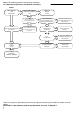
15.6 Ignition Control
IT IS IMPORTANT THAT ONLY THE CORRECT
IGNITION CONTROL SPECIFIED FOR EACH
MODEL TYPE IS USED WHEN REPLACING
THESE ITEMS.
15.6.1 S4565C
This control plugs onto the gas valve. Pull out 12 pin
electrical connection. Pull out ignition cable and
flame probe cable noting their positions
Release screw securing control to gas valve
Refit in reverse. Ensure correct location of ignition
and flame probe cables. Ensure that the earth
connection is made directly to the earth point on the
gas valve.
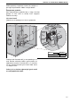
15.7 CTUA Axial Fan/Guard/Motor Assembly
The Axial fan unit for the CTUA heater is
supplied completely assembled and balanced.
15.7.1 Fan Removal and Replacement
15.7.2 To Replace the Fan Assembly
To replace the fan assembly, reverse the procedure
shown above. Fit rubber washers to the guard
mountings to reduce vibration.
• Check that the fan blades are free to rotate
before turning on the power to the fan.
• Strictly comply with the colour code of the fan
wires to ensure correct operation. See Page 14,
Section 9.3and Section 9.4 wiring diagrams
• Use only genuine ROBERTS GORDON
®
replacement parts.
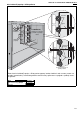
15.7.3 To Replace the Fan(s)
To reassemble, reverse the procedure shown above.
• Fit new rubber seal between the fan flange and
the heater rear panel.
• Fit to the rear panel in the correct orientation.
• Strictly comply with the colour code of the fan
wires to ensure correct operation. See Page 14,
Section 9.3 and Section 9.4
wiring diagrams.
• Use only genuine ROBERTS GORDON
®
replacement parts.
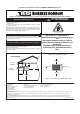
15.8 Combination Fan/Limit Thermostat
15.8.1 Removal and Replacement
1. Pull off the electrical connections to the
thermostat
2. Unscrew the two screws securing the
thermostat
3. Fit a new thermostat ensuring that the correct
temperature setting and type are selected.
See Page 6, Section 4.3 through Page 7, Fig-
ure 2.
4. Reconnect the electrical connections and test
operation.
Remove the screws
and washers.
Description Part Number
Axial Fan CTCU-7 11111910
Axial Fan CTCU-11 11111911
Axial Fa n C T C U - 15 111119 2 0
Axial Fa n C T C U - 2 2 111119 2 1
Uputstvo za instaliranje, puštanje u rad, rukovanje i održavanje
15.6 Kontrola paljenja
Ova kontrola vezuje se na gasni ventil. Izvucite12-to
delnu električnu konekciju. Izvucite kabel paljenja i
kabel sonde paljenja (pilota) označivši prethodno
njihove pozicije. Odvrnite zavrtanj kojim je kontrola/
upravljač pri čvršćen(a) za ventil. Vratiti po redu.
Proverite da li ste kabel paljenja i sonde plamena
vratili u odgovarajući položaj. Proverite da li je dobro
postavljena veza uzemljenja.
15.7 Motor CTCUA aksijalnog ventilatora
Aksijalni ventilator CTUA zagrejača je u potpunosti
opremljen i uravnotežen.
15.7.1 Skidanje i zamena ventilatora
Uklonite zavrtnjeve i
podmetače
15.7.2 Zamena ventilatora
Da biste zamenili ventilator obrnite gore pokazanu
proceduru. Postavite gumene zaptivače u cilju
smanjenja vibracija.
• Proverite da li lopatice ventilatora mogu slobodno
da rotiraju pre puštanja u rad
• Striktno vodite računa o bojama (kodu boja) žica
kako bi se obezbedilo normalno funkcionisanje
Videti stranu 14, odeljak 9.3 dijagram el. vodova
• Koristite isključivo rezervne delove ROBERTS
GORDON
15.8 Limit termostat/termostat ventilatora
15.8.1 Uklanjanje i zamena
1. Odvojite električnu instalaciju
2. odvijte zavrtnjeve
3. Postavite novi termostat i proverite da li su
izabrani odgovarajući tip i temperaturaVideti stranu
6, odeljak 4.3
4. Ponovo povežite instalaciju i testirajte
Opis
Broj dela
Aksijalni ventilator CTCU-7
Aksijalni ventilator CTCU-11
Aksijalni ventilator CTCU-15
Aksijalni ventilator CTCU-22