
Service manual


SECTION 15: REMOVAL AND REPLACEMENT PARTS
27
SECTION 15: REMOVAL AND REPLACEMENT PARTS
See warnings and notes on Page 20, Section 12
before removing or replacing parts.
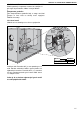
Burner Components
All serviceable burner parts are accessed by the
door on the right side of the heater. Use a
screwdriver to turn the latch 90°. See Page 5,
Section 4.
15.1 Gas Valve
Remove the gas supply pipe at the heater inlet.
15.1.1 Models 22 - 60
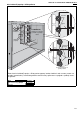
15.1.2 All Models
Replace in reverse order. Verify that the gas flow
direction of the valve is correct. Use a minimum
amount of gas seal on the thread joint. Check that
all the joints are leak free. Reset gas valve. See
Page 17, Section 10.4.2.
IT IS IMPORTANT THAT ONLY THE CORRECT
GAS VALVES SPECIFIED FOR EACH MODEL
TYPE ARE USED WHEN REPLACING THESE
CONTROLS.
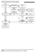
Disconnect
wire harness
Unplug
control
from
valve.
Remove
fixing
screw.
Ignition
Control
Description Part Number
Gas Valve VR4105A 90033403
Ignition Control 90434010
ODELJAK 15: UKLANJANJE I ZAMENA DELOVA
ODELJAK 15: UKLANJANJE I ZAMENA DELOVA
Videti upozorenja i napomene nastrani 20, Odeljak 12
pre nego što počnete da skidate i menjate delove.
Komponente gorionika
Svim komponentama gorionika koje se mogu servisirati
pristupa se kroz vrata na desnoj strani zagrejača.
Uklonite 4 zavrtnja.
15.1 Gasni ventil
Uklonite cev za dovod gasa na ulazu u grejno telo.
Vratiti po redu. Proverite da li je smer protoka gasa u
redu. Koristite minimalnu količinu gasne plombe na
zglobovima/sastavima. Proverite da li na sastavima
curi gas. Ponovo postavite gasni ventil. Videti stranu
17, Odeljak 10.2.2
Važno je da se koriste odgovarajući gasni ventili
za svaki pojedinačni model.
Kontrola
paljenja
Odvojiti
kontrolu
od
ventila
Odvrnuti
fiksirajući
zavrtanj
Iskopčati
žice
Opis
Broj dela
Gasni ventil VK4105A
Kontrola paljenja