
Service manual


SECTION 9: WIRING AND ELECTRICAL INFORMATION
13
SECTION 9: WIRING AND ELECTRICAL INFORMATION
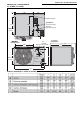
9.1 Electrical Supply
All heater models need a constant 230 V 50 Hz
single phase supply connected to terminals L, N &
Earth.
Polarity "L & N" must be correct. The voltage
between neutral and earth should be 0 and never
exceed 15 volts.
All heaters and controls must be correctly earthed.
All external wiring must comply with the relevant
local codes. Wire specification H05VV-F.
External controls must have the same constant
230 V 50 Hz supply.
An isolator with a contact separation of at least
3 mm on all poles must be installed adjacent to, but
not attached to the heater to disconnect all supplies
to the heater and any remote control.
The final connection to the heater should be made
by flexible cable or conduit to the main terminal
block on the inside of the heater using 1 mm
2
cable
on all models.
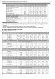
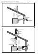
9.2 Remote Controls
The heater is designed to be operated by controls
installed remote from the heater. See Page 14,
Section 9.3.and Section 9.4.
9.2.1 Burner Controls (Thermostat)
Controls to operate the burner must be voltage free
contacts connected between terminals of the main
terminal block.
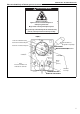
9.2.2 Positioning Room Thermostats or
ROBERTS GORDON
®
Control
A room thermostat or ROBERTS GORDON
®
control should be mounted on a wall or column at a
height of approximately 1.5 metres from the floor to
measure the ambient temperature. It should be clear
of both cold draughts and the direct path of warm air
from the heater.
9.2.3 Remote Frost Thermostat
When required, connect to terminals 2 and 3 in the
main terminal block.
Locate within the heated space adjacent to the most
vulnerable equipment that requires protection.
See Page 14, Section 9.3 and Section 9.4.
9.2.4 Remote Fan Controls
The fan will operate automatically providing there is
a constant 230 V supply to the main terminals.
A switch or control wired between terminals L & 1 in
the terminal block will allow external control of the
fan(s).
The fan may be controlled to operate continuously
from an external control, with the burner cycling on
and off, providing that the fan run-on at close down
is not impaired.
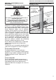
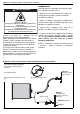
WARNING
Electrical Shock Hazard
Disconnect electrical power before servicing.
Failure to follow these instructions can result in
death or electrical shock.
ODELJAK 9: INFORMACIJE O STRUJI I ELEKTRIČNIM VODOVIMA
ODELJAK 9: INFORMACIJE O STRUJI I ELEKTRIČNIM VODOVIMA
9.1 Dovod struje
Svi modeli zagrejača zahtevaju 230 V 50 Hz
monofazni izvor struje povezan sa kontaktima L, N i
zemljom.
L & N moraju se poklapati. Napon između nule i
zemlje mora biti 0 i ne bi trebalo da pređe 15 volti.
Svi zagrejači i kontrole moraju biti na odgovarajući
način uzemljeni. Spoljašnji električni vodovi moraju
biti u skladu sa važećim lokalnim propisima.
Specifikacija H05VV-F.
Spoljašnje kontrole moraju imati isto, konstantno
napajanje od 230 V 50 Hz.
Izolator od najmanje 3mm na svim polovima mora
biti instaliran blizu, ali ne uz zagrejač da se ne bi
sprečilo snabdevanje ili daljinska kontrola.
Krajnju vezu sa zagrejačem predstavlja fleksibilan
kabel ili cev prema glavnom kontaktnom bloku
unutar grejnog tela sa kablom od 1mm, za sve
modele.
9.2 Daljinska kontrola
Grejno telo je projektovano tako da može da
funkcioniše daljinskim upravljanjem.Videti stranu 14,
Odeljak 9.3
9.2.1 Upravljanje gorionikom (termostat)
Upravljači gorionika moraju biti kontakti bez napona
povezani između L1 i T2.
9.2.2 Postavljanje sobnih termostata ili ROBERTS
GORDON kontrole
Sobni termostar ili ROBERTS GORDON kontrola
treba da se postave na zid ili na stub visine od oko
1.5 m. Ne bi trebalo da se nalazi niti na mestu gde je
promaja niti na mestu izloženom direktnom udaru
toplog vazduha iz zagrejača.
Opasnost od električnog udara
Isključite struju pre servisiranja
Nepridržavanje ovih uputstava može rezultirati
smrću ili električnim udarom.
UPOZORENJE
9.2.3 Daljinski termostat hlađenja (frost
thermostat)
Kada je potrebno povežite sa kontaktima 2 i 3 u
glavnom kontaktnom bloku. Postavite u okviru
grejnog prostora uz opremu kojoj je neophodna
zaštita.Videti stranu 14, odeljak 9.3
9.2.4 Daljinsko upravljanje ventilatorom
Ventilator će funkcionisati automatski pod uslovom
da su glavni kontakti konstantno snabdeveni
naponom od 230 V. Prekidač ili kontrola između
kontakta L1 i T1 u kontaktnom bloku omogućiće
spoljašnju kontrolu ventilatora.
Ventilator može biti trajno kontrolisan spolja, sa
gorionikom na poziciji on ili off, pod uslovom da
ventilator pri gašenju nije oštećen.