
Infrared Heating System Owner's Manual
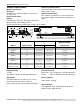

ROBERTS GORDON
®
CRV-SERIES SUBMITTAL SHEET
© 2004 Roberts-Gordon
BEFORE INSTALLATIO N AND OPERATI ON OF HEATIN G EQUI PMENT, READ AND UNDERSTAND THE I NSTALLATION, O PERATION AND SERVICE MANUAL.
APPLICATIONS, ENGIN EERING AND DETAI LED GUIDANCE ON SYST EMS DESIGN, INSTALLATION AND PRODUCT PERFORMANCE IS AVAILABLE UPO N REQUEST. ROBERTS GORDON
®
PRODUCTS ARE TO BE
INSTALLED ONLY I N ACCOR DANCE WIT H LOCAL LAW S, CODES AND REGULATIONS, AND ONLY BY A CONTRACTO R QUALIFIED IN THE INST ALLATION AND SERVICE OF GAS-F IRE D HEAT ING EQUIPMEN T.
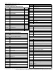
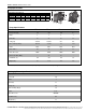
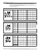
CLEARANCES TO COMBUSTIBLES
NOTE: 1. All di mensions are from the surfaces of all tubes, couplings, elbows, tees and crosses.
2. Clearances B, C and D can be reduced by 50% after 25' (7.5 m) of tubing downstream from
where the combustion chamber and the tube connect.
3. “-” indicates an unapproved application. Roberts-Gordon prohibits the installation of this
heater for all unapproved applications.
* Protective Grille clearances are the same as Standard Reflector.
.
Standard Reflector*
(inches) (centimeters)
Model ABCDABCD
CRV-B-2 4 20 48 20 11 51 122 51
CRV-B-4 4 20 48 20 11 51 122 51
CRV-B-6 4 20 48 20 11 51 122 51
CRV-B-8 4 20 48 20 11 51 122 51
CRV-B-9 4 36 60 36 11 92 153 92
CRV-B-10 4 36 60 36 11 92 153 92
CRV-B-12 4 36 60 36 11 92 153 92
CRV-B-12A 4 36 60 36 11 92 153 92
B
C
D
A
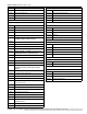
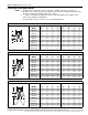
One Side Reflector
(inches) (centimeters)
Model ABCDABCD
CRV-B-2 4 12 56 20 11 31 143 51
CRV-B-4 4 12 56 20 11 31 143 51
CRV-B-6 4 12 56 20 11 31 143 51
CRV-B-8 4 12 56 20 11 31 143 51
CRV-B-9 4 12 60 42 11 31 153 107
CRV-B-10 4 12 60 42 11 31 153 107
CRV-B-12 4 12 60 42 11 31 153 107
CRV-B-12A 4 12 60 42 11 31 153 107
A
B
C
D
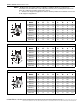
Two Side Reflectors
(inches) (centimeters)
Model ABCDABCD
CRV-B-2 4 12 56 12 11 31 143 31
CRV-B-4 4 12 56 12 11 31 143 31
CRV-B-6 4 12 56 12 11 31 143 31
CRV-B-8 4 12 56 12 11 31 143 31
CRV-B-9 4 12 60 12 11 31 153 31
CRV-B-10 4 12 60 12 11 31 153 31
CRV-B-12 4 12 60 12 11 31 153 31
CRV-B-12A 4 12 60 12 11 31 153 31
A
B
C
D