
Infrared Heating System Owner's Manual

ROBERTS GOR DON
®
CRV-SERIES SUBMITTAL SHEET
© 2004 Roberts-Gordon
BEFORE IN STALLATI ON AND OPER ATION OF HEATI NG EQUIPMENT, READ AND U NDERSTAND THE INSTALLATION, OPERATIO N AND SERVICE MANUAL.
APPLICATION S, ENGI NEERING AND DETAI LED GUID ANCE ON SYSTEMS DE SIGN, INSTAL LATION AND PRODUCT PERFORMANCE IS AVAILABLE UPON REQUEST. ROBERT S GORDON
®
PRODUCTS ARE TO BE
INSTALLED ONLY IN ACCORDANCE WITH LOCAL LAWS, CODES AND REGUL ATIONS, AND ONLY BY A CONTRACTOR QUALIFIED I N THE INSTALLATION AND SERVICE OF GAS-FIRED HE ATING EQUI PMENT.
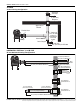
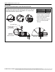
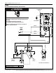
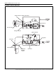
EP-200 Series Horizontal Venting Configurations
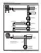
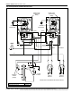
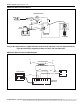
EP-300 Series Horizontal Venting Configurations
10' (3 m) Maximum and No Elbows
25' (8 m) and 3 Elbows Maximum
50' (15 m) and 3 Elbows Maximum
4" (10 cm) Single Wall Pipe
5" (12.5 cm) Single Wall Pipe
6" (15 cm) Single Wall Pipe
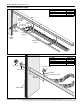
Bird
Screen
6" to 4" Reducer
(15 cm to 10 cm)
Vent Terminal
Tjernlund VH1-6
Vent Terminal
Tjernlund VH1-6
Approved Thimbles
Vent Terminal
Tjernlund VH1-4
4" (10 cm) Vent Terminal
18" (46 cm) Minimum -
40" (102 cm) Maximum
5" to 4" Reducer
(12.5 cm to 10 cm)
6" to 5" Reducer
(15 cm to 12.5 cm)
18" (46 cm) Minimum -
40" (102 cm) Maximum
10' (3 m) Maximum and 1 Elbow
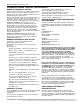
Thimble
Vent Terminal
Tjernlund VH1-
6" (15 cm)
or Equivalent
(Not Included)
6" (15 cm)
Bird Screen
(Included)
18" (46 cm) Minimum -
40" (102 cm) Maximum
10' (3 m) Maximum and 1 Elbow
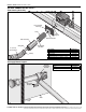
6" (15 cm)
Band Clamp
Single Wall Pipe/Tube 6" (15 cm)
Pitch single wall pipe
downward away from pump
1/4" every 10' (3 m).