
Infrared Heating System Owner's Manual

ROBERTS GORDON
®
CRV-SERIES SUBMITTAL SHEET
© 2004 Roberts-Gordon
BEFORE INSTALLATIO N AND OPERATI ON OF HEATIN G EQUI PMENT, READ AND UNDERSTAND THE I NSTALLATION, O PERATION AND SERVICE MANUAL.
APPLICATIONS, ENGIN EERING AND DETAI LED GUIDANCE ON SYST EMS DESIGN, INSTALLATION AND PRODUCT PERFORMANCE IS AVAILABLE UPO N REQUEST. ROBERTS GORDON
®
PRODUCTS ARE TO BE
INSTALLED ONLY I N ACCOR DANCE WIT H LOCAL LAW S, CODES AND REGULATIONS, AND ONLY BY A CONTRACTO R QUALIFIED IN THE INST ALLATION AND SERVICE OF GAS-F IRE D HEAT ING EQUIPMEN T.
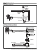
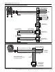
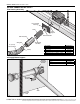
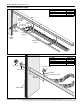
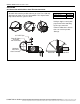
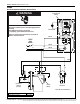
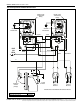
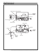
VENTING
Vertical Venting Configuration
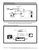
HORIZONTAL VENTING 4" (10 CM) PIPE
EP-100 Horizontal Venting Configurations
Approved
Vent Cap
Approved
Thimble
2' (610 mm)
Minimum
Aluminized Tee
1" (250 mm)
P.V.C to drain
system in
accordance
with local
codes.
Drain Cap
Clamps
Flexible Boot
6"(150 mm)
20" (510 mm) for EP-300
25' (8 m) and 3 Elbows Maximum
50' (15 m) and 3 Elbows Maximum
Bird
Screen
4" (10 cm) Single Wall Pipe
5" (12.5 cm) Single Wall Pipe
Vent Terminal
Tjernlund VH1-4
Vent Terminal
Tjernlund VH1-6
Approved Thimbles
5" to 4" Reducer
(12.5 mm to 10 cm)
6" to 5" Reducer
(15 cm to 12.5 cm)
18" (46 cm) Minimum -
40" (102 cm) Maximum
18" (46 cm) Minimum -
40" (102 cm) Maximum