
Infrared Heating System Owner's Manual

ROBERTS GOR DON
®
CRV-SERIES SUBMITTAL SHEET
© 2004 Roberts-Gordon
BEFORE IN STALLATI ON AND OPER ATION OF HEATI NG EQUIPMENT, READ AND U NDERSTAND THE INSTALLATION, OPERATIO N AND SERVICE MANUAL.
APPLICATION S, ENGI NEERING AND DETAI LED GUID ANCE ON SYSTEMS DE SIGN, INSTAL LATION AND PRODUCT PERFORMANCE IS AVAILABLE UPON REQUEST. ROBERT S GORDON
®
PRODUCTS ARE TO BE
INSTALLED ONLY IN ACCORDANCE WITH LOCAL LAWS, CODES AND REGUL ATIONS, AND ONLY BY A CONTRACTOR QUALIFIED I N THE INSTALLATION AND SERVICE OF GAS-FIRED HE ATING EQUI PMENT.
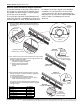
Coupling and Tube Assembly (Continued)
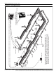
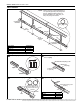
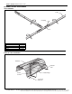
ELBOW PACKAGE CONFIGURATION
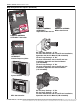
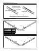
Elbow Installation
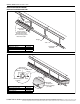
Elbow Installation (continued)
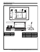
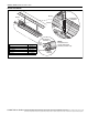
Incorrect Slide Bar
position
Correct Slide Bar
dimensions
± 2" (5 cm)
Drive Slide Bar until tight.
End of Slide Bar should be
within tolerance listed below.
Repeat A - D until all tubes are assembled.
NOTE: If Coupling is not tight, loss of vacuum can occur.
Tighten Slide Bar as shown below.
Tube
90° Elbow
Coupling
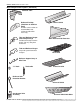
Description Part Number
Elbow Package 02718702
90° Elbow 01335801
Coupling 01312700
Reflector End Cap 02750800
Reflector Joint Piece 02750900
U-Clip Package 91107720
Tube
Coupling