
Infrared Heating System Owner's Manual

ROBERTS GORDON
®
CRV-SERIES SUBMITTAL SHEET
© 2004 Roberts-Gordon
BEFORE INSTALLATIO N AND OPERATI ON OF HEATIN G EQUI PMENT, READ AND UNDERSTAND THE I NSTALLATION, O PERATION AND SERVICE MANUAL.
APPLICATIONS, ENGIN EERING AND DETAI LED GUIDANCE ON SYST EMS DESIGN, INSTALLATION AND PRODUCT PERFORMANCE IS AVAILABLE UPO N REQUEST. ROBERTS GORDON
®
PRODUCTS ARE TO BE
INSTALLED ONLY I N ACCOR DANCE WIT H LOCAL LAW S, CODES AND REGULATIONS, AND ONLY BY A CONTRACTO R QUALIFIED IN THE INST ALLATION AND SERVICE OF GAS-F IRE D HEAT ING EQUIPMEN T.
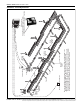
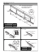
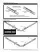
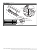
Tube Installation
Coupling and Tube Assembly
Combustion
Chamber
7' 6"
(229 cm)
Combustion
Chamber
NOTE: Tubing requires a downward slope of
1/2" (13 mm) per 20' (6 m) away from
burner. Tailpipe Tubing requires a
downward slope of 1" (26 mm) per
20' (6 m) away from burner.
10'
maximum
(3 m)
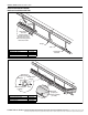
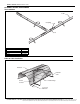
End View
Weld
Seam
Bottom
of Tube
Hanger
Turnbuckles
Tube
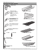
Description Par t Number
Tube 91409XXX
Turnbuckle 91903201
Tube/Ref lector Hanger 03090100
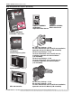
Tube
Tube
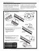
Orient coupling so that
the impact block is in the
2:00 or 10:00 oclock
positions
Closed
Open
Tab
3" (8 cm) to
4" (10 cm)
Slide Bar/Coupling Lock
Coupling
Wide end
Coupling
Tube
Slide Bar/Coupling Lock
A
Close coupling with tab
B
Start slide bar/coupling lock
onto coupling
C
Insert tubes into coupling
D
Tighten coupling to join tubes
Descr iption Part Number
Coupling 01329600
Slide Bar/Coupling Lock 01329700
Tube 91409XXX