
Service manual


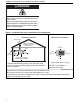

TABLE OF FIGURES
Figure 1: Installation Clearances and Clearances
to Combustibles.........................................................4
Figure 2: Suspension Methods ................................................. 7
Figure 3: Shelf Mounting and Hanging Suspension.................. 8
Figure 4: Vertical Louvers (Optional).........................................9
Figure 5: Vent and Roof Detail ................................................ 12
Figure 6: Standard Vented Heater -
Vertical and Horizontal Vent Termination................. 13
Figure 7: Standard Vented Heater -
Common Vertical Vent Termination ......................... 13
Figure 8: Separated Combustion Heater -
Vertical and Horizontal Vent Termination................. 14
Figure 9: Concentric Vent Box................................................. 14
Figure 10: Concentric Vertical and Horizontal Vent
Termination - Separated Combustion Heater ......... 15
Figure 11: Gas Connection...................................................... 17
Figure 12: Automatic Burner Control Sequence......................23
Figure 13: Gas Valve for Models UH (A) (AS) 30 - 45.............23
Figure 14: Gas Valve for Models UH (A) (AS) 60 - 125 .........24
Figure 15: Manual Reset Limit Switch .....................................26
Figure 16: LED Diagnostic Codes........................................... 27