
Service manual


COMBAT
®
UH UNIT HEATER INSTALLATION OPERATION AND SERVICE MANUAL
38
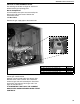
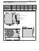
14.4 Combustion Fan Vertical Installation
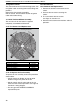
IT IS IMPORTANT THAT ONLY THE CORRECT COMBUSTION FAN SPECIFIED FOR EACH MODEL
TYPE IS USED WHEN REPLACING THESE ITEMS.
Carry out a start-up after working on or changing a combustion fan. See Page 26, Section 11.
MODEL UH [A] [AS] 30 UH [A] [AS] 45 UH [A] [AS] 60 UH [A] [AS] 75 UH [A] [AS] 100 UH [A] [AS]125
Exhaust Fan P/N 90710404 90710404 90710404 90710404 90710405 90710405
Gasket
Mounting Plate
to Vent Box
fixing screws
Intake &
Exhaust
Covers
Air Intake Adapter
Flexible Duct
Vent Box
Gaskets
Mounting Plate
to Vent Box
fixing screws
Mounting Plate
to Flue Fan
fixing screws
Air Intake
Adapter
Intake &
Exhaust Covers
To remove the fan, remove
screws securing the fan and
mounting plate to the vent box.
To remove the fan from the
mounting plate, remove screws.
Refit in reverse order.
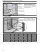
To change the vent and air
intake orientation from back to
top, remove the fan and
mounting plate as above.
Remove intake and exhaust
covers from top of the heater.
Rotate the fan, mounting plate
and gasket clockwise until the
flue adapter lines up with the
top hole. Secure screws.
Remove the flexible duct from
the air intake adapter on the
back.
Remove the air intake adapter
from the back of the heater and
install in the appropriate hole on
top. Reconnect the flexible duct.
Install intake and exhaust
covers over the back holes.